Gain control circuit, and a radio communication apparatus using the same

a gain control circuit and radio communication technology, applied in the direction of gain control, power management, wireless communication, etc., can solve the problems of large circuit scale of agc amplifiers and increase in current consumption, and achieve the effect of expanding the linear range of variable gain circuits

Inactive Publication Date: 2005-04-05
SONY CORP
View PDF8 Cites 4 Cited by
  • Summary
  • Abstract
  • Description
  • Claims
  • Application Information

AI Technical Summary

Benefits of technology

Compensation of the non-linearity is done in a range where the linearity of gain control characteristic is lost. As a result, the linear range of the variable gain circuit can be expanded, so that the linearity extends to the range where linearity is conventionally lost in the gain control characteristic of a gain control circuit.

Problems solved by technology

As a result, the circuit scale of the AGC amplifier becomes large and current consumption increases too.

Method used


Image

  • Gain control circuit, and a radio communication apparatus using the same
  • Gain control circuit, and a radio communication apparatus using the same
  • Gain control circuit, and a radio communication apparatus using the same

Examples


first embodiment

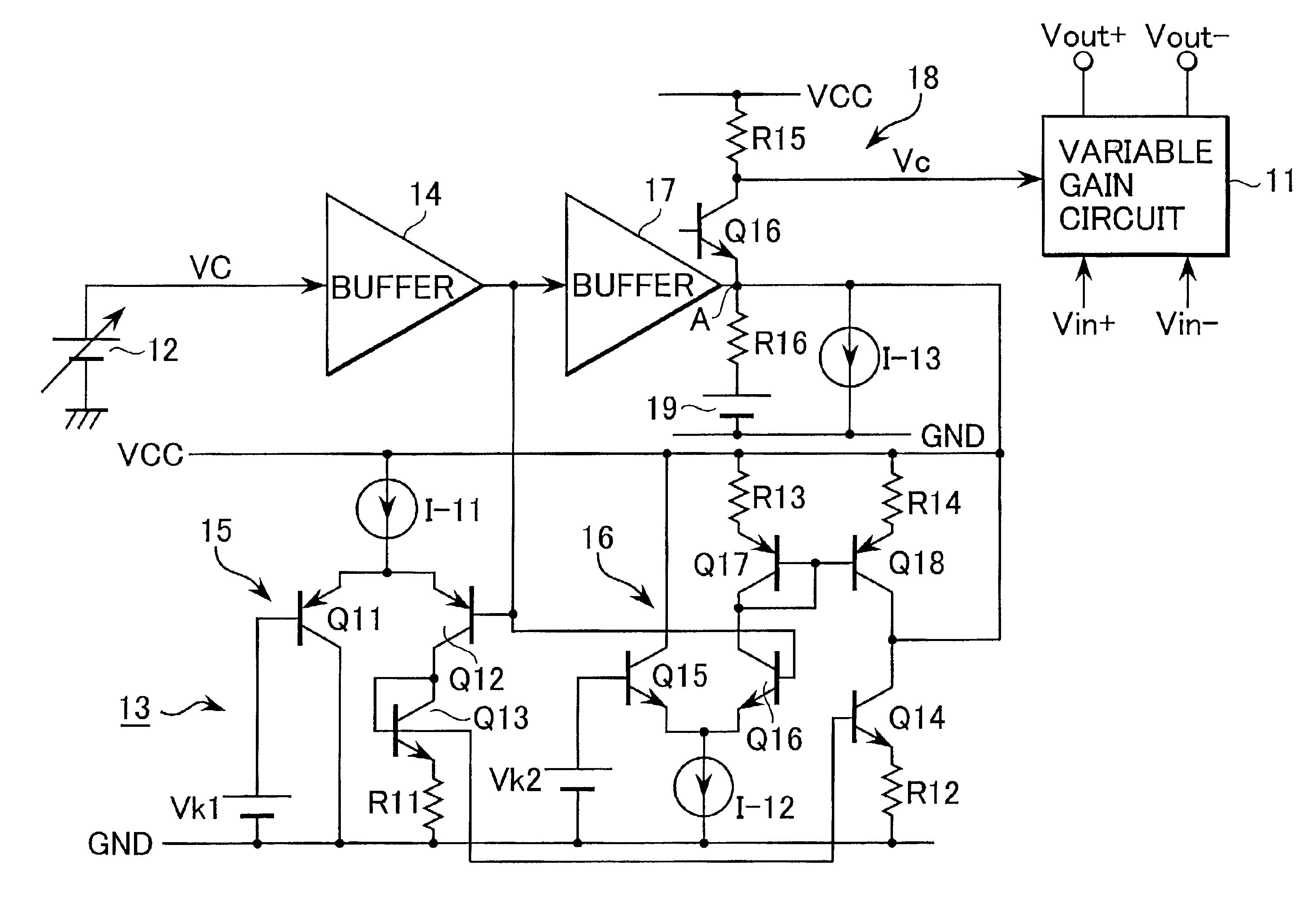
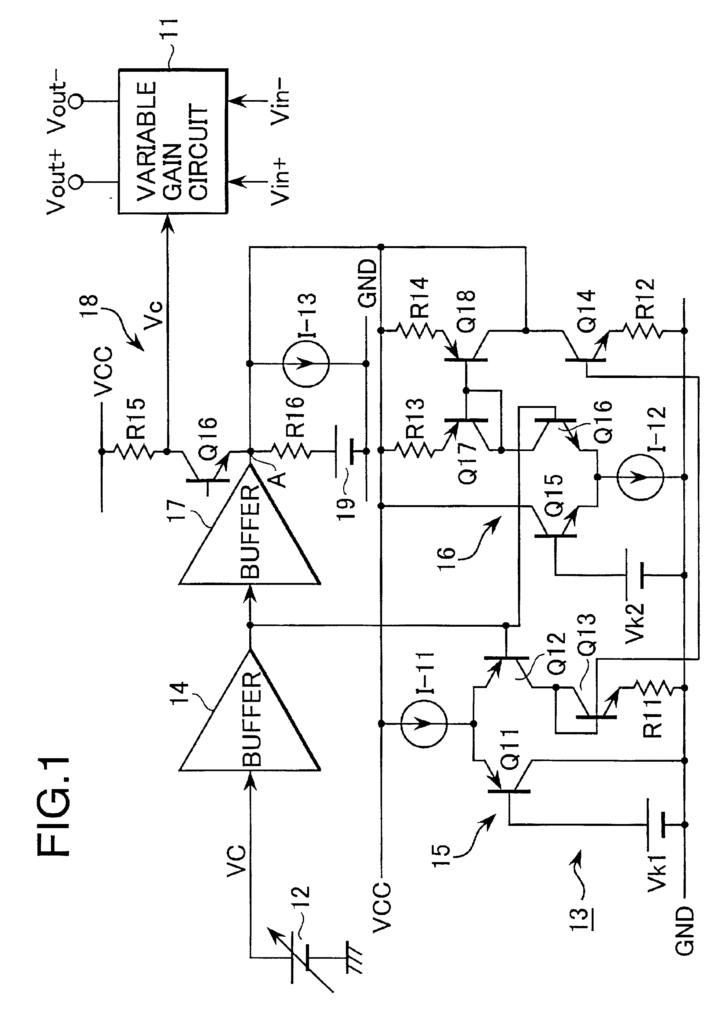
Detailed descriptions of preferred embodiments of the present invention are described with reference to the accompanying drawings as follows. FIG. 1 is a circuit diagram showing a construction of a gain control circuit related to the present invention.

A gain control circuit, according to the present invention, comprises a variable gain circuit 11 having a limited variable gain range and a control voltage supply circuit 13, wherein the control voltage supply circuit 13 receives an external control voltage VC from an external control voltage generating source 12 and converts this external control voltage VC into an internal control voltage Vc to be supplied to the variable gain circuit 11 as a gain control voltage.

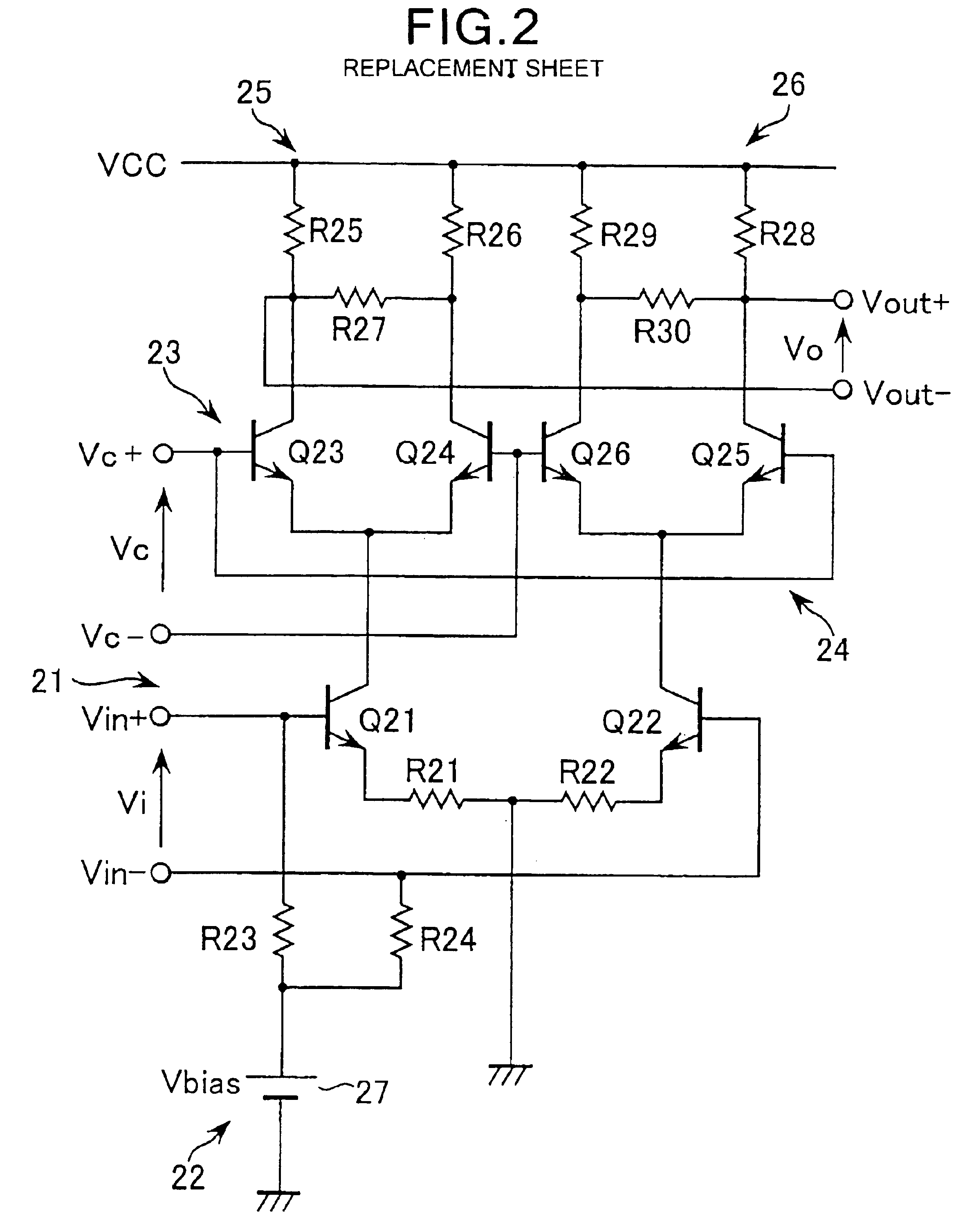
As the variable gain circuit 11, a circuit having the same circuit construction as the variable gain circuit related to the conventional embodiment shown in FIG. 6 is used. In other words, the variable gain circuit 11 comprises a differential amplifying circuit 21, a bias ci...

second embodiment

FIG. 4 is a block diagram showing a construction of a gain control circuit related to the present invention.

The gain control circuit related to the embodiment comprises a plurality of cascade-connected variable gain circuits 31, 32 and 33, each having differential input and output, and a control voltage supply circuit 35 to supply internal control voltages Vc1, Vc2 and Vc3 to the variable gain circuits 31, 32 and 33, respectively, wherein these internal control voltages Vc1, Vc2 and Vc3 are generated based on a given external control voltage VC from an external control voltage generating source 34.

Each of variable gain circuits 31, 32 and 33 has a limited variable gain range and is connected mutually by way of buffer circuits 36 and 37. These variable gain circuits 31, 32 and 33 have gain control terminals VC 1, VC 2 and VC 3, respectively, and the internal control voltages Vc1, Vc2 and Vc3 set in the control voltage supply circuit 35 are supplied to these gain control terminals VC ...


PUM


Abstract

A gain control circuit comprises a variable gain circuit having a predetermined gain control range and a control voltage supply circuit for supplying an internal control voltage to the variable gain circuit as a gain control signal. In this gain control circuit, the control voltage supply circuit generates the internal control voltage in response to an external control voltage so as to compensate the linearity of the variable gain circuit to the extent of the external control voltage where the variable gain circuit loses linearity. This gain control circuit is applied to an AGC circuit of the transmitting stage in a CDMA-type mobile phone.

Description

BACKGROUND OF THE INVENTION1. Field of the InventionThe present invention relates to a gain control circuit and a radio communication apparatus using such gain control circuit, and more particularly the present invention relates to a gain control circuit to be used for an output power control in a mobile radio communication apparatus and to a radio communication system using such mobile radio communication apparatus.2. Description of the Related ArtIn a mobile radio communication system, for example, in a mobile telephone system, it is desirable that the output power of each mobile terminal is controlled so as to be received with the same signal strength at a base station, in order to increase the communication capacity of the base station.In particular, in a communication system in which the mobile telephone system employs a spectrum scattering method referred to as a CDMA (Code Division Multiple Access) system, plural stations are assigned to the same frequency band, and a receive...

Claims


Application Information

Patent Timeline
Patent Type & Authority Patents(United States)
IPC IPC(8): H03G3/30H04B7/005H03G1/04H04B1/04
CPCH03G3/3042H04W52/52
Inventor MOROHASHI, HIDEOTANABE, SHINICHI
Owner SONY CORP
Why Eureka
Try Eureka