
Manufacturing method and device of non-homogeneous entity

A manufacturing method and technology for manufacturing equipment, applied in the direction of ceramic extrusion dies, etc., can solve problems such as poor flexibility, low precision, and layer limit, and achieve high forming accuracy, simple process and manufacturing equipment, and flexible material addition methods Effect

Inactive Publication Date: 2013-09-11
HEBEI UNIV OF TECH
View PDF1 Cites 0 Cited by
  • Summary
  • Abstract
  • Description
  • Claims
  • Application Information

AI Technical Summary

Problems solved by technology

Although this technology can achieve gradient changes in materials, it can only manufacture structures with insignificant gradient changes in materials, and the number of layers of gradient changes formed is limited, with poor flexibility and low precision.

Method used


Image

  • Manufacturing method and device of non-homogeneous entity
  • Manufacturing method and device of non-homogeneous entity
  • Manufacturing method and device of non-homogeneous entity

Examples


Embodiment 1

[0052] A solid oxide fuel cell with a length of 50 mm and a diameter of 3 mm is manufactured by using the manufacturing method and equipment described in the present invention. Set the material addition method in the material information addition control software to linear mode, and the nozzle diameter is 100 μm. The process is as follows:

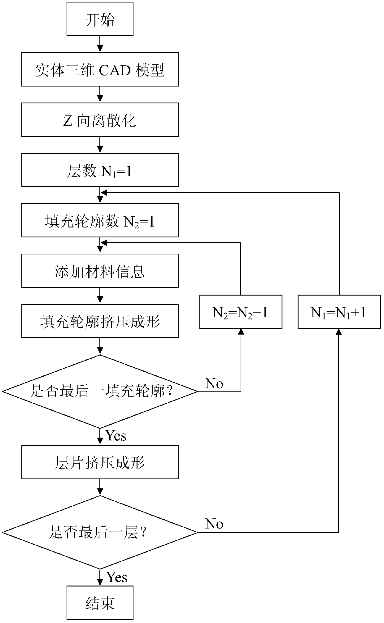
[0053] Firstly, the three-dimensional solid model of the solid oxide fuel cell is designed by using three-dimensional CAD software (see figure 1 ), and then according to the product design process requirements, it is sliced ​​and layered according to the design layer thickness. The number of layers is 500, and the slice thickness of each layer is 100 μm. By controlling the opening and closing time of the two-position two-way solenoid valve 210 in the forming head 2, various material component slurries are proportioned and then flow into the pre-mixing storage chamber 217, and the gas pre-mixing storage chamber 217 Under the action of pre...

Embodiment 2

[0056] It is basically the same as Example 1. The difference is that if the material addition method in the material information addition control software is set to be nonlinear, the uniformity of the gradient change of the electrolyte layer material of the prepared solid oxide fuel cell is increased by 25%, which greatly improves the performance of the solid oxide fuel cell. practicability.

Embodiment 3

[0058] It is basically the same as Example 1. The difference is that if the material addition method in the material information addition control software is set to a combination of linear and nonlinear, the prepared solid oxide fuel cell has a 40% increase in the uniformity of the gradient change of the electrolyte layer material, which not only greatly improves the The practicability of the solid oxide fuel cell further reduces the layer shedding phenomenon caused by the poor bonding between the anode layer and the cathode layer during sintering of the solid oxide fuel cell.


PUM

PropertyMeasurementUnit
diameteraaaaaaaaaa
diameteraaaaaaaaaa

Abstract

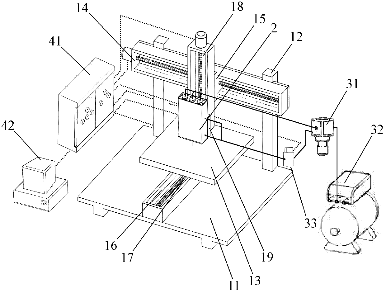
The invention provides a manufacturing method and device of a non-homogeneous entity. The manufacturing method comprises the following steps: 1, firstly slicing and layering a formed entity according to a designed thickness to obtain two-dimensional laminate information of each layer; 2, under the control of an application program, mixing the separation slurry in different material components in a material supply cavity in proportion according to the information requirement by a mixing extruding forming head to obtain a manufacturing slurry; c, under the control of CAD (computer-aided design) software, finishing the manufacturing of the first laminate of the entity by the mixing extruding forming head so that the material components in the two-dimensional laminate continuously changes in gradient along an appointed direction; 4, moving the height of one laminated in the formed entity by the mixing extruding forming head to finish the manufacturing of a second laminate of the entity; 5, repeating above method, performing one layer by one layer until the non-homogeneous entity is obtained. The manufacturing device provided by the invention is suitable for the manufacturing method provided by the invention, comprises a three-dimensional movement control platform, a multi-component material mixing extruding forming head, a gas supply and pressure control device and a control system.

Description

technical field [0001] The invention belongs to advanced manufacturing technology, specifically a method and equipment for manufacturing a heterogeneous entity. Background technique [0002] With the development of science and technology, higher requirements have been put forward for the performance of various parts. Usually, parts of a single (homogeneous) material cannot meet various almost harsh service conditions. The Institute of Aeronautics and Astronautics of the Japan Science and Technology Agency proposed the concept of functionally graded materials (Functionally Graded Materials, FGMs) in 1987, that is, the continuous transition of components or structures of multiple materials can simultaneously possess the excellent properties of several different materials. However, traditional material preparation methods can only form entities with a single gradient distribution direction and simple structure. The emergence of rapid prototyping (Rapid Prototyping) technology ...

Claims


Application Information

Patent Timeline
Patent Type & Authority Patents(China)
IPC IPC(8): B28B3/26
Inventor 徐安平蔡晓刚朱东彬刘志华
Owner HEBEI UNIV OF TECH
Learn More