
Connector for memory card

A memory card and connector technology, which is applied in the direction of connection, parts of the connection device, coupling device, etc., and can solve the problems of high and thin connectors for memory cards, etc.

Inactive Publication Date: 2012-02-08
SMK CO LTD
View PDF6 Cites 0 Cited by
  • Summary
  • Abstract
  • Description
  • Claims
  • Application Information

AI Technical Summary

Problems solved by technology

As a result, the inner diameter of the circular shape 104a of the bearing hole 104 is enlarged relative to the pivot axis of the circular cross-section, which becomes an obstacle to reducing the height of the memory card connector 100.

Method used


Image

  • Connector for memory card
  • Connector for memory card
  • Connector for memory card

Examples


Embodiment Construction

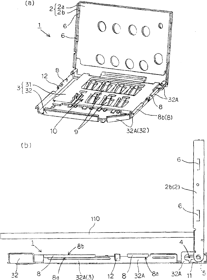
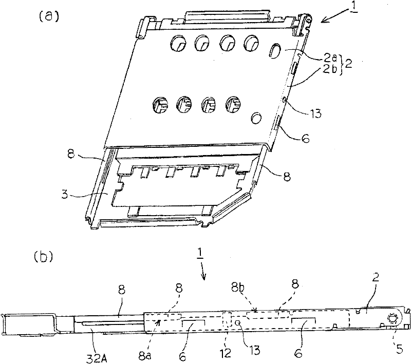
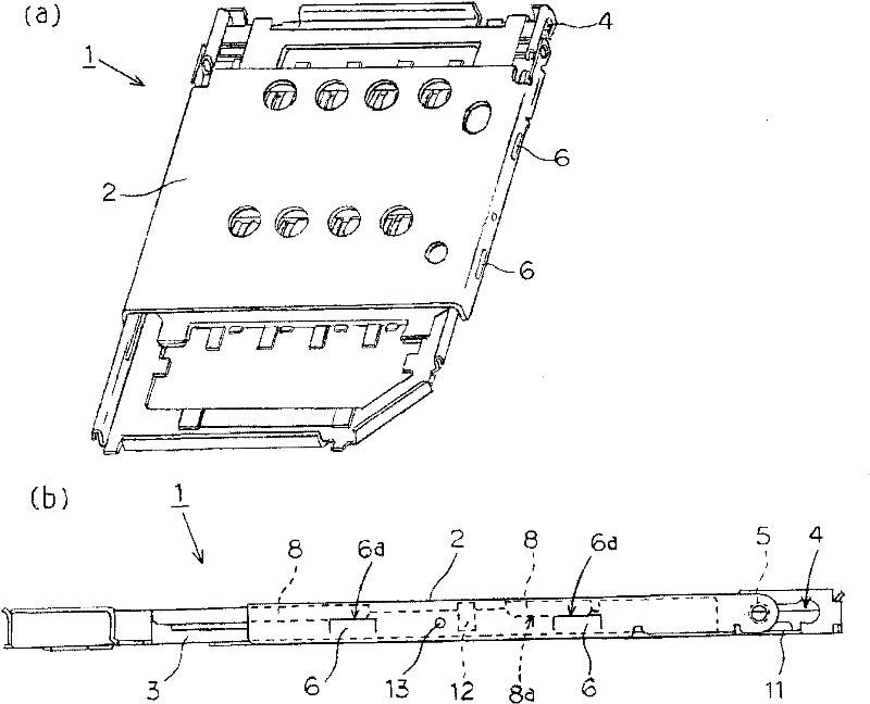
[0056] Next, use Figure 1 to Figure 11 A memory card connector 1 according to an embodiment of the present invention will be described. For a description of each part of the memory card connector 1, in figure 1 In (b), the up-down direction is defined as the up-down direction, the right side is defined as the front, and the left side is defined as the rear. The memory card uses connector 1 by Figure 4 The case body 3 shown in (a), the plurality of contacts 9 mounted on the case body 3 and the upper surface of the case body 3 are covered, Figure 5 The cover 2 shown in (a) is constituted.

[0057] Additionally, if Figure 4 As shown in (a), the housing main body 3 is formed by bending a metal plate into a rectangular frame shape surrounding the periphery of the memory card 110 mounted from above, and is fixed and mounted on a metal frame 32 surrounded by the metal frame 32. The inner side of the rectangular plate-shaped insulating base 31 constitutes. Therefore, a card...


PUM


Abstract

The invention provides a connector for memory cards, wherein the rotating support part of a pivot shaft and a bearing hole and a locking part for limiting the rotation of a cover are not damaged even during misoperation. According to the connector for memory cards, a bearing hole in the main body of a housing is formed in such a contour that the opening position of the pivot shaft of a cover on one side of the bearing hole and any position of a locking position on the other side of the bearing hole are freely rotatable. For a cover that is moved from the opening position to the locking position due to misoperation, the upper surface of the upper locking part of the main body of the housing is set to be an inclined surface and the upper surface of the lower locking part abutting upwards is guided to be clamped with the lower surface of the upper locking part. Therefore, the rotation of the locked cover is correctly performed.

Description

technical field [0001] The present invention relates to a memory card connector for connecting a memory card accommodated in an accommodating portion to an electronic device. The card is positioned in the memory card connector within the card housing. Background technique [0002] Now, there is well known a connector for a memory card in which a cover that is rotatable relative to the case main body is opened and the memory card is accommodated in the card accommodating portion of the case main body to cover the memory card accommodated in the card accommodating portion. The cover is closed by means of the upper surface, and the rotation of the cover is restricted in the closed state. For the memory card accommodated in the card accommodation portion, the contacts facing the card accommodation portion from the housing main body are electrically connected to the conductive pads on the bottom surface of the memory card, and are positioned between the locked cover and the hous...

Claims


Application Information

Patent Timeline
Patent Type & Authority Applications(China)
IPC IPC(8): H01R12/70H01R13/502H01R13/639
Inventor 江尻孝一郎
Owner SMK CO LTD
Learn More