Hydraulic control of a dual clutch transmission

A hydraulic controller, dual clutch technology, applied in clutch, transmission control, components with teeth, etc., can solve the problem of safe operation of transmission, and achieve the effect of reducing flow

Inactive Publication Date: 2012-02-08
HOFER MECHATRONIK
View PDF18 Cites 10 Cited by
  • Summary
  • Abstract
  • Description
  • Claims
  • Application Information

AI Technical Summary

Problems solved by technology

In particular, dual clutch transmissions present problems with the safe operation of the transmission due to the large number of control elements or due to the complex construction of one or more control elements

Method used


Image

  • Hydraulic control of a dual clutch transmission
  • Hydraulic control of a dual clutch transmission
  • Hydraulic control of a dual clutch transmission

Examples


Embodiment Construction

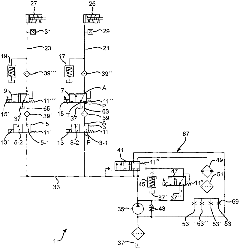
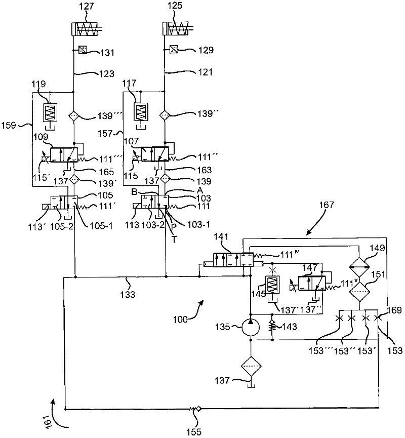
[0152] figure 1 and figure 2 An excerpt of the hydraulic system of a dual clutch transmission is shown. figure 2 Shown is a hydraulic controller 100 similar to figure 1 Hydraulic controller 1 shown in , which will be discussed below.

[0153] figure 1 The hydraulic controller 1 shown is composed of various components such as the hydraulic oil preparation circuit 67 and the controllers of the clutches 25 , 27 . The pressure supply line 33 can be regarded as the central line of the hydraulic controller. The centrally arranged pressure supply line 33 supplies hydraulic medium to subsequent lines, for example branch-shaped subsequent lines which ensure the supply of hydraulic oil to the clutches 25 , 27 . Various loads, such as clutches 25, 27, can be separated via valves 3, 5, for example, can be deactivated. The valve 3 has a first state 3-1 and a second state 3-2, the spring force of the spring 11 makes the preferential first state 3-1 hold time and the time when the e...


PUM


Abstract

The hydraulic controller includes couplings that are arranged separately in a hydraulic line, where a pressure supply line is fixed between proportional control valves. The proportional control valves are centrally located with pressure supply line. Additional separation layer forming valves are also provided that are decoupled with the pressure supply line.

Description

technical field [0001] The present invention relates to a transmission having a plurality of clutches which may be arranged in a dual clutch form, a hydraulic control system and components suitable for such a hydraulic transmission control system (such as proportional regulating valves) and a suitable transmission hydraulic system run method. Background technique [0002] Multi-clutch transmissions in automobiles are primarily referred to as "dual-clutch transmissions" and there are numerous variant types denoted by this concept, which differ primarily in the number of gears (e.g. whether there are six, seven or more forward gear), how to realize the way and method of reverse gear in the transmission, and the working mode of the transmission. [0003] Some dual-clutch transmissions can be referred to, for example, by printed instructions. For example, FR 2848629B1 (patent applicant: Renault SAS; application date: December 12, 2002) suggests that the same shift fork can be ...

Claims


Application Information

Patent Timeline
Patent Type & Authority Applications(China)
IPC IPC(8): F16H61/12F16H61/38F16H61/688
CPCF16D2048/0233F16D48/0206F16D2048/0278F16H61/0206F16H61/688F16D2048/029F16D2048/0293
Inventor R·瑙曼T·施特立
Owner HOFER MECHATRONIK
Why Eureka
Try Eureka