
Heat-source system and method for controlling the same

A technology of heat source system and control unit, which is applied in the direction of heating mode, heating and ventilation control system, heating and ventilation safety system, etc. It can solve the problems of efficiency increase, overall efficiency increase of heat source system, and large power consumption of cooling tower fans. Achieve efficient heat source system operation, realize heat source system operation, and reduce cooling water flow

Active Publication Date: 2012-02-01
MITSUBISHI HEAVY IND THERMAL SYST
View PDF5 Cites 8 Cited by
  • Summary
  • Abstract
  • Description
  • Claims
  • Application Information

AI Technical Summary

Problems solved by technology

If the cooling water temperature drops, the power consumption of the turbo chiller can be reduced and the efficiency can be expected to increase
On the other hand, if the number of activated cooling towers is increased, the power consumption of the cooling tower fans will increase, so it is conceivable that the overall efficiency of the heat source system will decrease.
Alternatively, it is also conceivable to increase the overall efficiency of the heat source system by reducing the power consumption of the turbo refrigerator instead of relatively reducing the increase in the power consumption of the cooling tower fan.

Method used


Image

  • Heat-source system and method for controlling the same
  • Heat-source system and method for controlling the same
  • Heat-source system and method for controlling the same

Examples


Embodiment Construction

[0048] Hereinafter, embodiments of the present invention will be described with reference to the drawings.

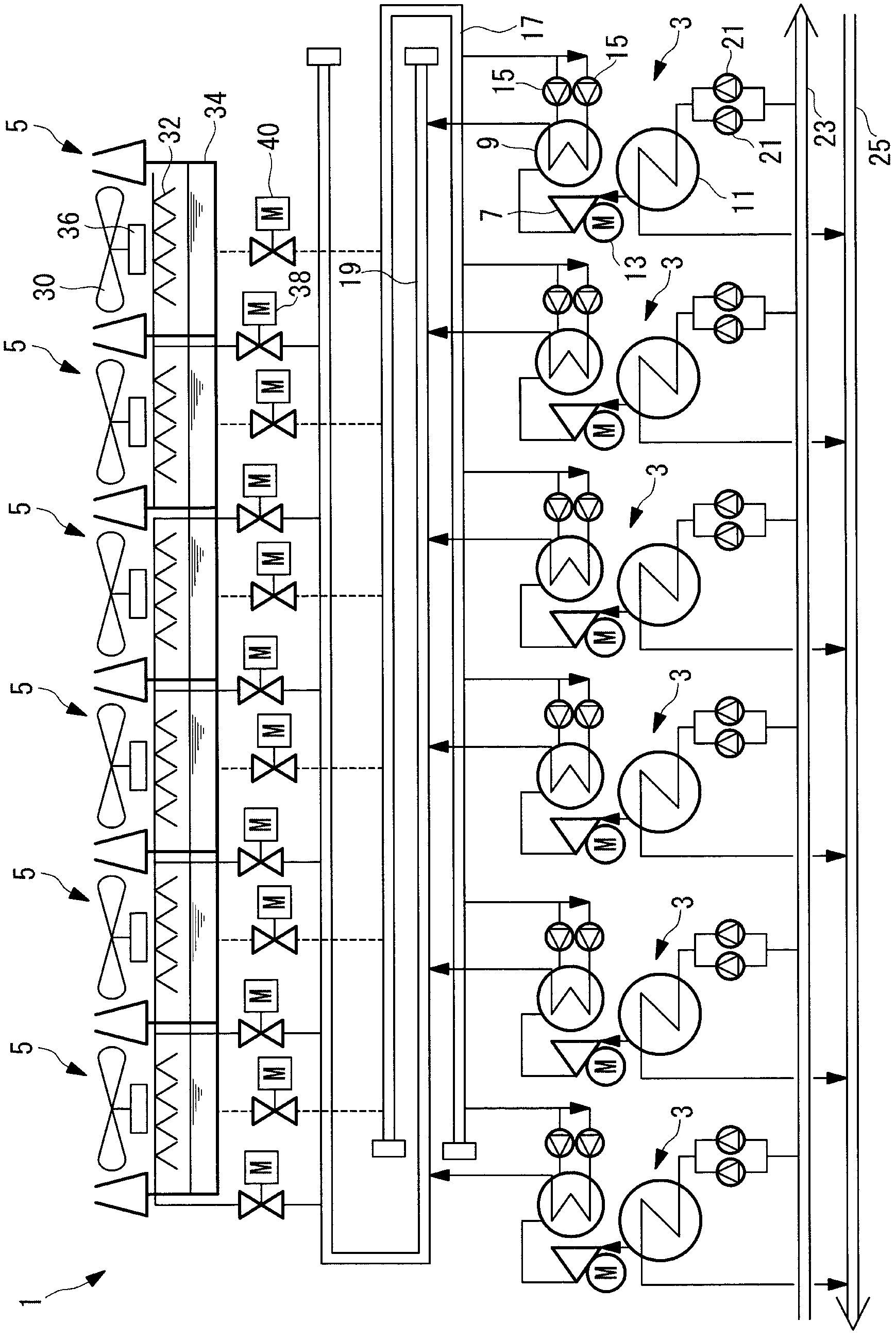
[0049] figure 1 One embodiment of the heat source system of the present invention is shown. The heat source system 1 includes a plurality of (six in this embodiment) turbo refrigerators 3 arranged in parallel, and a plurality of (six in this embodiment) cooling towers 5 arranged in parallel.

[0050] The turbo refrigerator 3 includes a turbo compressor 7 that compresses refrigerant, a condenser 9 that condenses and liquefies the refrigerant compressed by the turbo compressor 7 , and an expansion valve (not shown) that expands the refrigerant condensed and liquefied by the condenser 9 . Figure), the evaporator 11 that evaporates the refrigerant expanded by the expansion valve.

[0051] The turbo compressor 7 is driven by an electric motor 13 whose rotational frequency can be varied by inverter means.

[0052] Cooling water supplied by a cooling water pump 15 is introd...


PUM


Abstract

A heat-source system includes centrifugal-chillers, cooling-water pumps, cooling towers, cooling-tower fans, chilled-water pumps, and a control unit for controlling them. A plurality of the cooling towers are provided so as to have a cooling-tower capacity corresponding to the total capacity of the rated capacities of the respective centrifugal-chillers, the cooling towers being commonly connected to the plurality of centrifugal-chillers. The control unit preliminarily prepares an optimum cooling-tower capacity relationship representing the cooling-tower capacity with which the heat-source system efficiency, taking into consideration the centrifugal-chillers, the cooling-water pump, the cooling towers, the cooling-tower fan, and the chilled-water pump, is higher, in relation to the outside-air wet-bulb temperature and the centrifugal-chiller partial load factor. The control unit determines the number of cooling towers to be operated by referring to the optimum cooling-tower capacity relationship, on the basis of the outside-air wet-bulb temperature and the partial load factor of the centrifugal-chillers during operation.

Description

technical field [0001] The present invention relates to a heat source system that improves the overall efficiency of the heat source system and a control method thereof. Background technique [0002] As a heat source system used in cold water supply or district cooling and heating facilities in semiconductor factories, there is known a system including a plurality of turbo chillers that can be started and stopped according to the heat demanded by an external load. The heat source system includes, in addition to the turbo refrigerator, a cooling water pump for supplying cooling water to the condenser of the turbo refrigerator, and a system for cooling the cooling water heated up by recovering condensation heat from the condenser with the outside air. A cooling tower and a chilled water pump that supplies chilled water cooled by the evaporator of the turbo chiller to an external load. In addition, a cooling tower fan for introducing outside air into the cooling tower is provi...

Claims


Application Information

Patent Timeline
IPC IPC(8): F24F11/02F25B1/053
CPCF28F27/00F25B49/027F28C2001/006F28B9/06F25B2400/06F25B1/053F25B2700/2106
Inventor 上田宪治
Owner MITSUBISHI HEAVY IND THERMAL SYST
Learn More