
All fiber filter

A filter, all-fiber technology, applied in the fields of optics and laser optoelectronics, can solve the problems of filter bandwidth dependence, non-tunable, difficult to control, etc., to avoid insertion loss and alignment difficulties, easy to use all-fiber, and easy to adjust the modulation depth. Effect

Inactive Publication Date: 2012-02-01
TSINGHUA UNIV
View PDF4 Cites 6 Cited by
  • Summary
  • Abstract
  • Description
  • Claims
  • Application Information

AI Technical Summary

Problems solved by technology

The common feature of these schemes is that the filtering bandwidth depends on the performance of the device itself, which is not easy to control or tune.

Method used


Image

  • All fiber filter
  • All fiber filter
  • All fiber filter

Examples


Embodiment Construction

[0024] The specific implementation manners of the present invention will be further described in detail below in conjunction with the accompanying drawings and embodiments. The following examples are used to illustrate the present invention, but are not intended to limit the scope of the present invention.

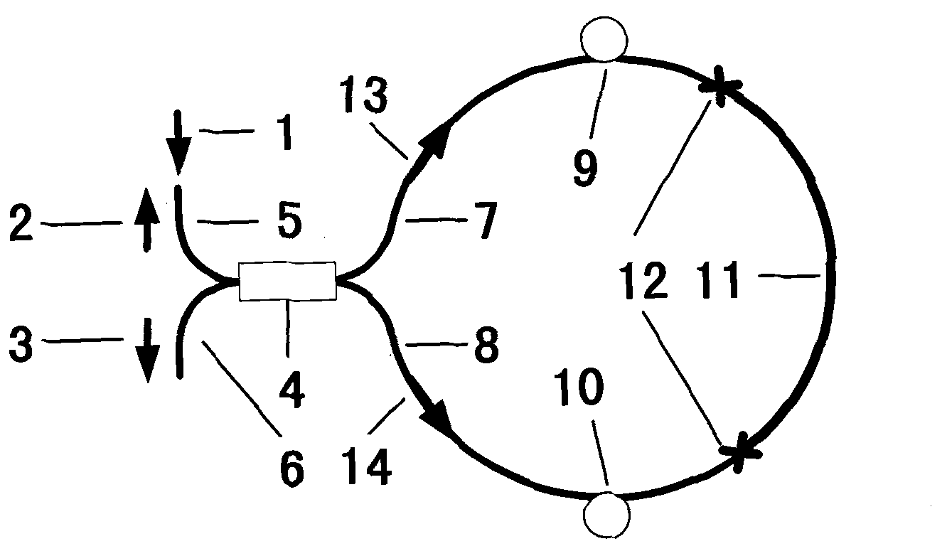
[0025] Such as figure 1 As shown, the structure of the all-fiber filter controlled by the fiber ring of the first embodiment of the present invention includes:

[0026] A 2×2 fiber optic coupler 4 having a first port and a second port on one side, and a third port and a fourth port on the other side;

[0027] A polarization-maintaining optical fiber 11, whose ends are respectively fused with the passive optical fibers 7, 8 of the third port and the fourth port, and the fusion point is 12, thereby forming a ring optical path;

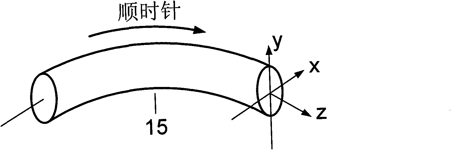
[0028] Wherein, the passive optical fiber 7 between the third port and the polarization maintaining optical fiber 11 is coiled into an optical fib...


PUM


Abstract

The invention discloses an all fiber filter. The filter comprises: a 2*2 fiber coupler, possessing a first port and a second port which are located on one side and a third port and a fourth port which are located on the other side; a polarization maintaining fiber, two ends of which are respectively welded with passive fibers of the third port and the fourth port so as to form an annular optical path. The passive fiber between the third port and the polarization maintaining fiber coils into a fiber ring possessing a certain radius. The fiber ring is taken as a first polarization controller. During introducing a block device, insertion losses can be generated and alignment is difficult. Bu using the all fiber filter, the above problems can be solved. An all-fiber system is easy to be realized. Filtering bandwidth is easy to be adjusted so that the all fiber filter is suitable for occasions with various different performance requirements.

Description

technical field [0001] The invention relates to the technical fields of optics and laser optoelectronics, in particular to an all-fiber filter. Background technique [0002] With the advent of the first low-loss optical fiber in 1970, fiber optic communications, high-power fiber lasers, etc. have made great progress in the past few decades. In fiber optic communication systems and fiber lasers, fiber filters play a very important role. For example, the dense wavelength division multiplexing technology in fiber optic communication networks relies on narrow-band comb filters; the tunable technology in fiber lasers also relies on tunable tuned filter. [0003] Traditional spectral filtering elements are interference filters or birefringent filters. These two block components can effectively filter, but because of their block shape, they destroy the all-fiber structure of the optical fiber system and cause large insertion loss. The schemes of all-fiber spectrum filters mainly...

Claims


Application Information

Patent Timeline
Patent Type & Authority Applications(China)
IPC IPC(8): G02B6/293G02B6/27G02B6/26G02B6/024G02B6/036
Inventor 巩马理周洁闫平张海涛王东生
Owner TSINGHUA UNIV
Learn More