
Precise positioning method and device of array layout

A technology of precise positioning and positioning devices, which is applied in the direction of measuring devices, satellite radio beacon positioning systems, instruments, etc., can solve the problems of positioning accuracy, GPS signal interference, and susceptibility to interference, and achieve low cost, improved efficiency, and structural simple effect

Active Publication Date: 2012-02-01
INST OF EARTHQUAKE CHINA EARTHQUAKE ADMINISTRATION
View PDF1 Cites 11 Cited by
  • Summary
  • Abstract
  • Description
  • Claims
  • Application Information

AI Technical Summary

Problems solved by technology

If a wireless radio frequency module is used, in order to achieve its nominal communication distance, the antenna must be set up relatively high. When it is higher than the GPS antenna, it will interfere with the GPS signal and even cause the GPS receiver to fail to work normally.
Moreover, the communication quality cannot be guaranteed, and it is susceptible to interference; 2. The antenna mast of the GPS antenna has a certain height. During the movement, the unevenness or shaking of the site will have a certain impact on the positioning accuracy. In fact, centimeter-level positioning accuracy is difficult to achieve or guarantee; 3. The GPS signal at the target point needs to be of good quality. If there is no GPS signal or the signal is poor at the target point, the positioning task will actually be impossible to complete

Method used


Image

  • Precise positioning method and device of array layout
  • Precise positioning method and device of array layout
  • Precise positioning method and device of array layout

Examples


Embodiment Construction

[0028] The present invention will be further described below in conjunction with the embodiments and accompanying drawings.

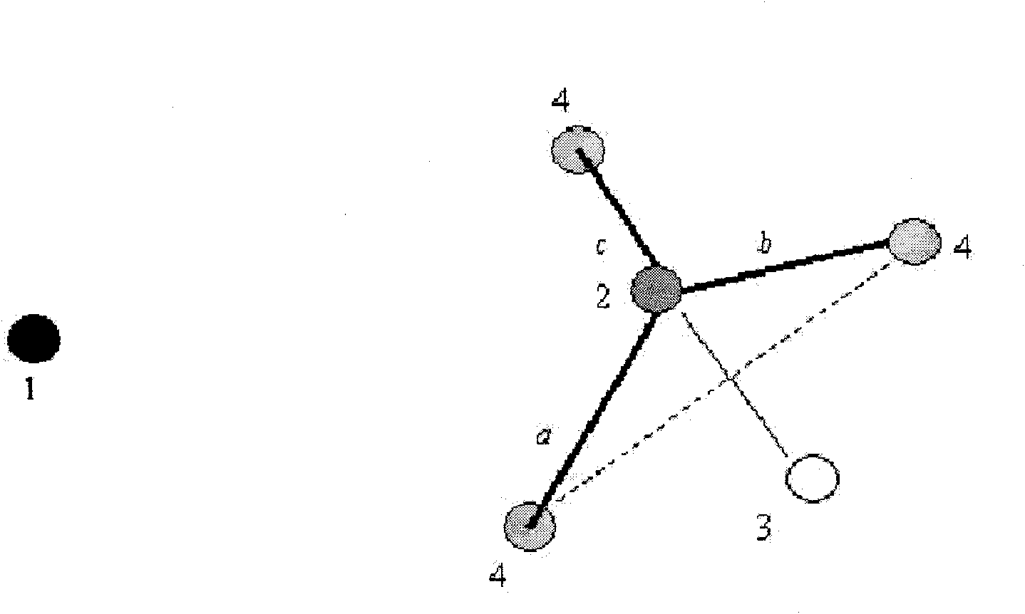
[0029] The precise positioning method and device for the layout of the platform array provided by the present invention, its positioning principle is as follows: figure 1 Shown: The positional relationship between the reference point 1 and the target point 2 is known by pre-design. The fixed control point 4 is set on the periphery of the target point 2, and it is generally advisable to set three, a, b and c represent the distance between the fixed control point 4 and the target point 2 respectively. First use the positioning device to measure the coordinates of the fixed control point 4. Then, with any two fixed control points as the benchmark, fix the endpoints of the measuring tape to the two fixed control points 4 with the length a+b as the length, and take the dividing point between the lengths of a and b on the measuring tape as the node, and Rul...


PUM


Abstract

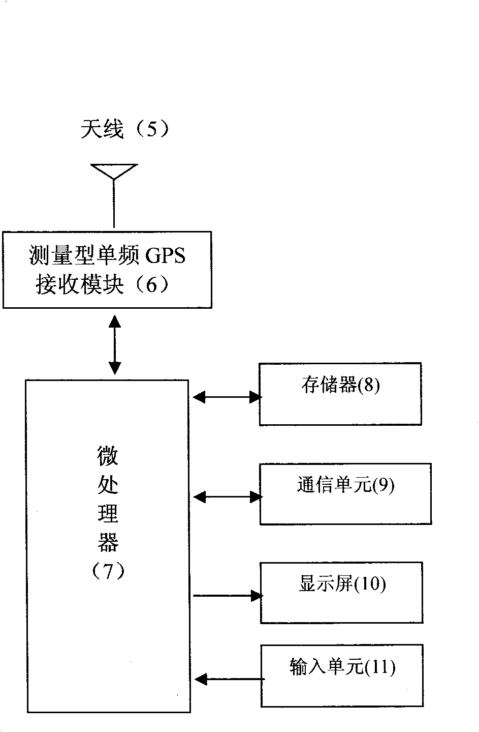
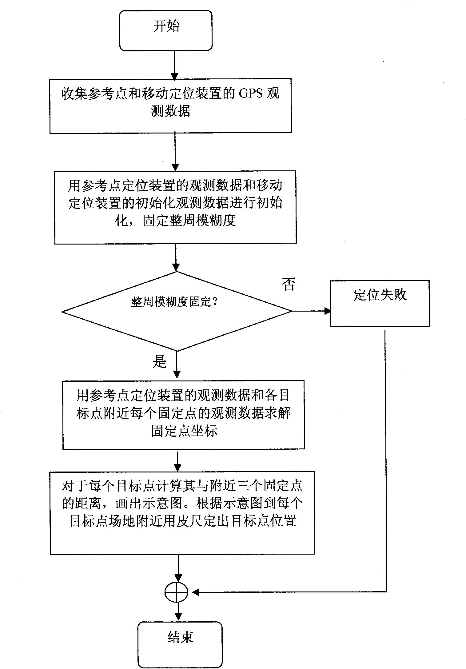
The invention relates to the fields of microtremor exploitation or other engineering vibration tests, and particularly relates to a precise positioning method and device of an array layout. A direct positioning process of a target point is divided into two processes of the positioning of three control points near the target point and positioning of the target point which is controlled by the three control points. The former adopts a GPS static baseline measuring method, and the latter adopts a measure tape measuring method. The invention combines the advantages of the two methods and realizes a precise, simple and reliable method. The invention also relates to two positioning devices for implementing the method, which includes a microprocessor, a single frequency measuring type GPS module, an input unit, a memorizer and a display screen, wherein one of the positioning devices is used for reference point observation and has the functions of storing and reading the GPS data, and the other one of the positioning devices is used for movement observation and also has the functions of target point setting, and graphic display.

Description

technical field [0001] The invention relates to the fields of micro-motion exploration and engineering vibration testing, in particular to a precise positioning method and device for the layout of micro-motion test bench arrays. Background technique [0002] In the field of micro-motion exploration and engineering vibration testing, in order to detect the vibration information in an area, many vibrators are often formed into an array, and the field signals are observed at the same time. There are certain constraints on the relative positional relationship of each observation point of the array. For example, the micro-motion spatial autocorrelation method requires the observation array to be circular, and the observation instruments at each point have good consistency. Generally, the correlation between the instruments is required. The sex is above 0.999, and the phase difference is within ±(3-5)°. That is, when the micro-movement surface wave phase velocity is at least 100m...

Claims


Application Information

Patent Timeline
Patent Type & Authority Applications(China)
IPC IPC(8): G01C15/00G01S19/43
Inventor 廖成旺邓涛丁炜王浩
Owner INST OF EARTHQUAKE CHINA EARTHQUAKE ADMINISTRATION
Learn More