
Installation process of upper module on offshore oil platform

A technology of offshore oil and installation technology, which is applied in the field of offshore oil engineering, can solve problems such as occupying a large space, greatly affecting safety, and shortage of floating crane resources, and achieves the effect of strong automation and easy operation

Active Publication Date: 2012-02-01
CHINA NAT OFFSHORE OIL CORP +2
View PDF4 Cites 20 Cited by
  • Summary
  • Abstract
  • Description
  • Claims
  • Application Information

AI Technical Summary

Problems solved by technology

[0004] 1. When using a large land crane for hoisting operations, it needs to occupy a large site space, which is significantly affected by the construction space of the construction site;
[0005] 2. For some upper modules, the distance from the edge of the offshore oil platform is relatively large. Large-scale land cranes cannot directly hoist the upper modules in place, and an additional sliding system is still required;
[0006] 3. For the heavy upper module, when the land crane is used for installation, it usually requires the joint operation of multiple large land cranes, and its safety is greatly affected by external factors;
[0007] 4. When using floating cranes for hoisting, it is required that the construction location of the offshore oil platform is close to the wharf, which has an important restrictive effect on the layout of the construction site; at the same time, the resources of floating cranes are relatively tight, and its operating costs are difficult to control

Method used


Image

  • Installation process of upper module on offshore oil platform
  • Installation process of upper module on offshore oil platform
  • Installation process of upper module on offshore oil platform

Examples


Embodiment Construction

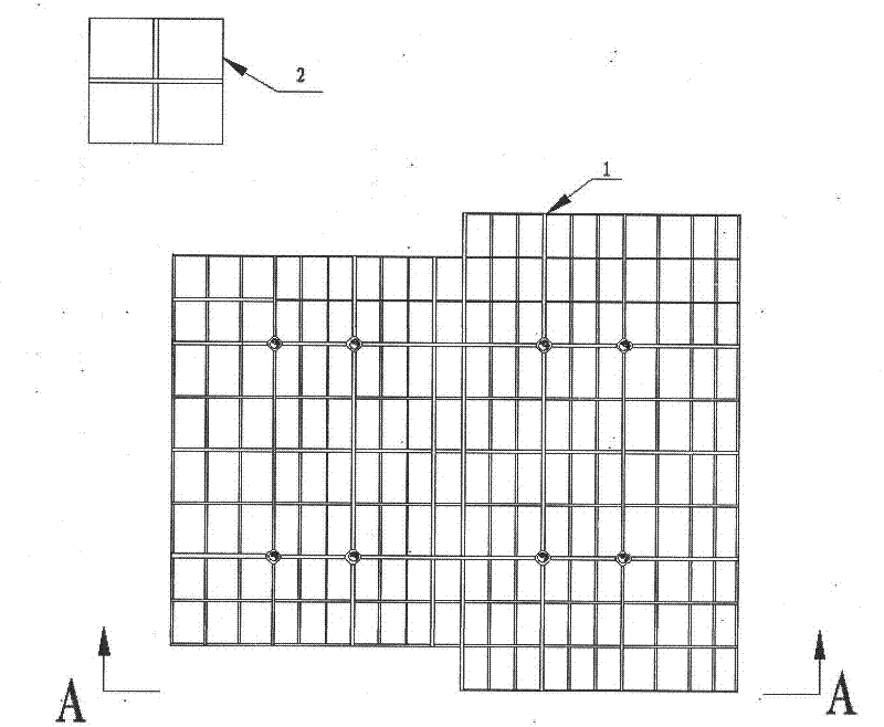
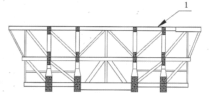
[0053] Such as figure 1 , figure 2 As shown, after the topside module 2 of the offshore oil platform is constructed in a different place, it will be transported to the construction site of the offshore oil platform 1 . Can adopt self-propelled hydraulic module car 12 to finish its loading and unloading operation as required.

[0054] The present invention is realized through the following steps:

[0055] The first step: the layout of the sliding track device

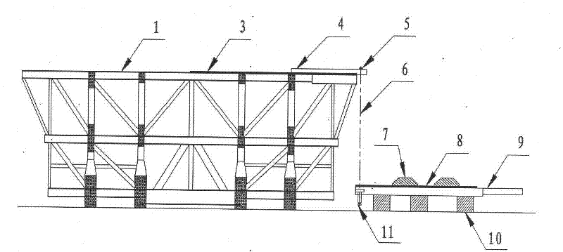
[0056] Such as figure 1 , figure 2 , image 3 , Figure 9 , Figure 10 , Figure 11As shown, when the upper module 2 needs to be installed during the construction process of the offshore oil platform 1, a sliding track device is arranged in the lifting operation area of ​​the offshore oil platform 1. The sliding track device includes: several sliding rails fixed on the offshore oil platform 1 Moving track 3, several upper support cantilever beams 4 connected with the main body of offshore oil platform 1, sever...


PUM


Abstract

The invention provides an installation process of an upper module on an offshore oil platform. The installation process comprises the following steps: (1) arranging a slipping track device in a platform lifting operation area; (2) transporting the upper module to a platform construction area and putting the upper module on the slipping track device; (3) arranging a hydraulic lifting and slipping device at one side of the slipping track device; (4) starting lifting operation; (5) after a slipping track to be lifted is parallel and level with a slipping track on the platform, stopping the lifting operation and connecting the two slipping tracks into a whole; (6) slipping the upper module to a set position; and (7) stopping slipping and putting the upper module on lower support structures tocomplete connection between the upper module and the lower support structures. The installation process has the following beneficial effects: accurate positioning of the upper module and installationoperation of the upper module in any position on the offshore oil platform can be achieved; at the same time, the installation process has no special requirements for the arrangement position of the site for offshore oil platform construction and is slightly affected by external factors; and the installation process is convenient for site operation and has the effects of lowering the operation cost and improving the operation safety.

Description

technical field [0001] The invention relates to a module installation process, in particular to an installation process for an upper module of an offshore oil platform, and belongs to the field of offshore oil engineering. Background technique [0002] There are two main types of offshore oil platforms: fixed platforms and floating platforms. A fixed offshore oil platform generally includes: an upper module and an underwater fixed support structure. This type of offshore oil platform is generally built separately on land with the upper module and the underwater fixed support structure. [0003] With the development of offshore oil engineering to deep water, the weight of offshore oil platforms is also increasing, and it will tend to be modularized. For large-scale structural monomers (such as living buildings, etc.), upper modules can be constructed separately in multiple sites. During the onshore construction of offshore oil platforms, the installation of the topside mod...

Claims


Application Information

Patent Timeline
IPC IPC(8): E02B17/00
CPCE02B17/00E02B17/027E02B2017/0039
Inventor 李淑民李林阮庆李黎霞杨风艳陈品吴航杨胜董文乙
Owner CHINA NAT OFFSHORE OIL CORP
Learn More