
Reciprocating type yarn jig dyeing machine

A technology of a reciprocating, jigger, used in yarn dyeing in the yarn-dyed industry. , In the field of reciprocating yarn jiggers, it can solve the problems of high production cost, laborious addition of dyeing liquid and yarn, and more dyeing liquid, etc., and achieve the effect of low production cost, low labor intensity and improved quality.

Inactive Publication Date: 2012-01-25
郑国洪
View PDF5 Cites 7 Cited by
  • Summary
  • Abstract
  • Description
  • Claims
  • Application Information

AI Technical Summary

Problems solved by technology

Since the cylinder of this dyeing equipment is vertically arranged, and its mouth is located on the upper part of the cylinder, it is laborious to add the dyeing solution and yarn, which makes the labor intensity of the operator relatively high.
Because this kind of dyeing equipment is to place the dyed yarn in the dyeing solution, the dyeing of the yarn is realized by soaking, and the dyed yarn is placed in the dyeing solution in a whole tube, not only the required dyeing solution is relatively Many, high production cost, and the inner and outer layers of the yarn tube are prone to color difference, which makes the quality of the dyed yarn lower

Method used


Image

  • Reciprocating type yarn jig dyeing machine
  • Reciprocating type yarn jig dyeing machine
  • Reciprocating type yarn jig dyeing machine

Examples


Embodiment Construction

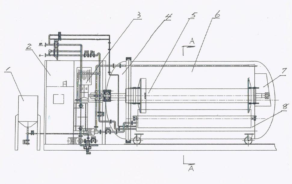
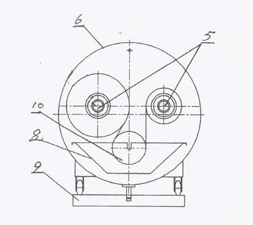
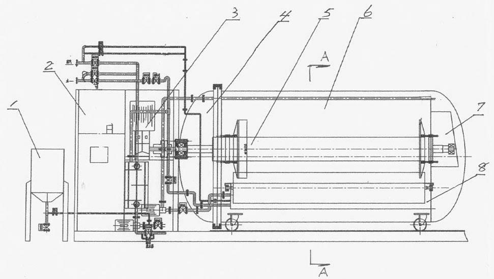
[0014] Such as figure 1 and figure 2 As shown, the reciprocating yarn jigger of the present invention includes a cylinder 6 arranged horizontally, one end of the cylinder 6 is closed, and the other end is equipped with a cylinder cover 4 that can be opened and closed. The cylinder body 6 is provided with a dye solution tank 8, which is a long tank, which is placed at the bottom of the cylinder body 6 inner cavity through a base 9, and two winding shafts 5 are arranged above it. The dye solution tank 8 and the two winding shafts 5 are parallel to each other, and brackets 7 are arranged in the cylinder body 6 at both ends of the dye solution tank 8. on bracket 7. The cylinder cover 4 is processed with a through hole, and the same end of the winding shaft 5 protrudes out after passing through the cylinder cover 4 of the cylinder body 6 and is connected with the output shaft of a power mechanism (motor and reducer) 3 respectively. The mouth of the dye liquor tank 8 is provided...


PUM


Abstract

The invention relates to a reciprocating type yarn jig dyeing machine which comprises a cylinder body and is characterized in that the cylinder body is arranged horizontally, and one end of the cylinder body is provided with a cylinder cover capable of being opened and closed. A dye vat is arranged in the cylinder body, two winding shafts are arranged above the dye vat, the dye vat and the winding shafts are parallel, the middles of the cylinder body at two ends of the dye vat are provided with brackets, and two ends of the winding shafts are respectively rotatably arranged on the two brackets. The same ends of the two winding shafts penetrate through the cylinder body and extend outside as well as respectively connected with an output shaft of a power mechanism. A transition roller is arranged on the mouth part of the dye vat, and two ends of a roller shaft of the transition roller can be rotatably arranged on upper edges of two ends of the dye vat. During working, yarns on one winding shaft are wound from the lower side of the transition roller, and then wound on the other winding shaft. By adopting the reciprocating type yarn jig dyeing machine, the labor intensity and the production cost of operators can be reduced, and the quality of dyed yarns can be improved. The reciprocating type yarn jig dyeing machine is suitable for yarn dyeing of yarn dye industries.

Description

technical field [0001] The invention relates to a dyeing device. Specifically, it is a reciprocating yarn jigger used for dyeing yarn, especially suitable for yarn dyeing in the yarn-dyed industry. Background technique [0002] At present, in the yarn-dyed industry, the dyeing equipment used to dye the yarn mainly includes a cylinder, which is vertically arranged, and there is a dyeing solution inside the cylinder. When dyeing, the dyed yarn is placed in the dyeing solution, and passed through Soaking to realize the dyeing of the yarn. Since the barrel of this dyeing equipment is vertically arranged, and its mouth is at the top of the barrel, it is laborious to add the dyeing solution and yarn, which makes the labor intensity of the operator relatively high. Because this kind of dyeing equipment is to place the dyed yarn in the dyeing solution, the dyeing of the yarn is realized by soaking, and the dyed yarn is placed in the dyeing solution in a whole tube, not only the re...

Claims


Application Information

Patent Timeline
IPC IPC(8): D06B3/32D06B3/06
Inventor 郑国洪
Owner 郑国洪
Learn More