
Electrical protection device and control method of the electrical protection device

A technology of protection device and control method, which is applied in the direction of emergency protection circuit device, circuit device, automatic disconnection emergency protection device, etc., to achieve the effect of simplifying installation

Inactive Publication Date: 2015-06-03
SIEMENS AG
View PDF8 Cites 0 Cited by
  • Summary
  • Abstract
  • Description
  • Claims
  • Application Information

AI Technical Summary

Problems solved by technology

The high warehouse management effort required is a disadvantage here

Method used


Image

  • Electrical protection device and control method of the electrical protection device
  • Electrical protection device and control method of the electrical protection device

Examples


Embodiment Construction

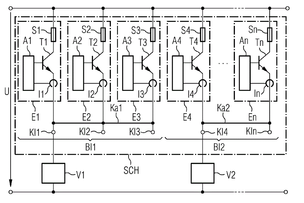
[0030] exist figure 1 shows a protective device SCH with a plurality of protective elements E1 . . . En. In this case, initially three protective elements E1, E2, E3 are combined to form a first protective device block B11 and the remaining protective elements E4...En are combined to form a second protective device block B12. The first load or load branch V1 is connected to the supply voltage U of the power supply via the first protective device block B11 and the second load or load branch V2 is connected to the supply voltage U of the power supply via the second protective device block B12.

[0031]Each protection element El...En includes a current limiting element Tl...Tn and a current detection unit I1...In. The corresponding current-limiting elements T1 . . . Tn are designed, for example, as transistors and the corresponding current detection units I1 . . . The current flow through the current-limiting elements Tl...Tn is controlled in dependence on the respective detect...


PUM


Abstract

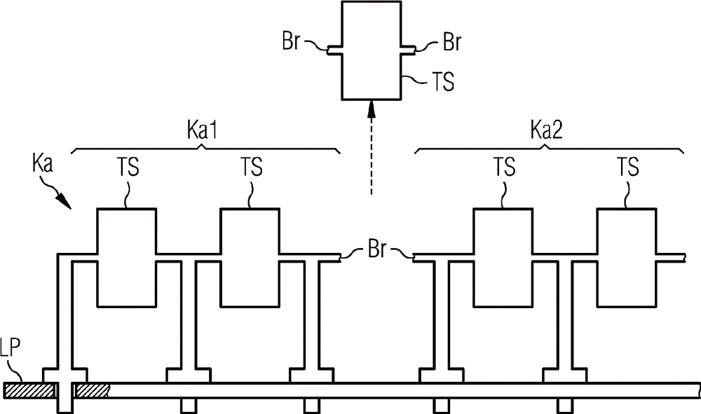
The protection device (SCH) has current-limiting or switching-off protection elements (E1-En) including outputs, which are connected in a parallel using a connecting ridge. The connecting ridge is provided with a manually separable disconnecting point (Br), which has a disconnecting piece. A marking is provided below a disconnecting point and / or the disconnecting piece for displaying ridge separation. Chip temperature of the protection elements is detected as a critical parameter. Control units (A1-An) determine contact resistances of current limiting elements (T1-Tn). An independent claim is also included for a control method of an electrical protection device.

Description

technical field [0001] The invention relates to an electrical protective device for being arranged between at least one load and a power source, wherein the protective device has a current limiting function and a disconnection function with an adjustable current limit value. Furthermore, the invention relates to a control method of an electrical protection device. Background technique [0002] Electrical protective devices are used everywhere where interference situations in electrical installations can lead to hazards for people and / or machines. Electrical protective devices are required in particular when a load or loads are supplied by means of a power supply. The electrical protective device is arranged between a power source and one or more loads in order to reduce the current through the one or more loads in the event of a disturbance and to open the circuit in the event of a persistent disturbance. [0003] For example, DE 101 49 458 C1 shows a protective device bet...

Claims


Application Information

Patent Timeline
Patent Type & Authority Patents(China)
IPC IPC(8): H02H3/087H02H7/26
CPCH02H7/26H02H3/025H02H3/087
Inventor T. 罗特迈尔H. 施韦格特
Owner SIEMENS AG
Learn More