
Fixture for conductivity test and assembling method thereof

A technology of conductivity and fixtures, which is applied in the field of test tools to achieve the effects of convenient comparison, simplification of assembly, and assurance of repeatability

Active Publication Date: 2012-01-18
安徽元隽氢能科技股份有限公司
View PDF3 Cites 14 Cited by
  • Summary
  • Abstract
  • Description
  • Claims
  • Application Information

AI Technical Summary

Problems solved by technology

[0003] Aiming at the deficiencies in the prior art, the present invention provides a fixture for conductivity testing and its assembly method, aiming to solve the problem of fixing and testing methods in the conductivity performance test of electrolyte materials, and at the same time, by introducing a modular kit design scheme, Making it a general-purpose electrolyte conductivity performance test fixture

Method used


Image

  • Fixture for conductivity test and assembling method thereof
  • Fixture for conductivity test and assembling method thereof
  • Fixture for conductivity test and assembling method thereof

Examples


Embodiment 1

[0047] This embodiment provides an assembly method of a jig for conductivity testing:

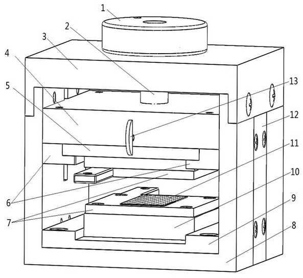
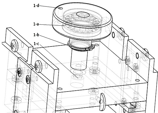
[0048] 1. Install the positioning head 1 with the plane bearing 1-a and the positioning stop screw, put it into the center hole of the fixed outer frame 3, and fix it with the shaft retaining ring 1-b;

[0049] 2. Fix the indenter with the upper insulating plate 5, and fix the indenter 4 and the screw rod 2;

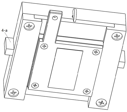
[0050] 3. Put the indenter into the fixed outer frame 8, fix the fixed outer frames 3 and 8, and fix the side plate 12 with the chute;

[0051] 4. Cooperate the indenter 4 with the positioning head 1;

[0052] 5. Fix the lower insulating plate 6 and the fixed outer frame 8;

[0053] 6. Fix the upper electrode plate 14 and the lower electrode plate 15 in the upper and lower insulating plates 5 and 10 respectively. And put the fixing knob 13 into the pressure head 4, and adjust the position to fix the upper insulating plate 5;

[0054] 7. Fix the electrode plate 7 and the external c...

Embodiment 2

[0057] This embodiment provides an assembly method of a jig for conductivity testing:

[0058] 1. Install the positioning head 1 with the plane bearing 1-a and the positioning stop screw, put it into the center hole of the fixed outer frame 3, and fix it with the shaft retaining ring 1-b;

[0059] 2. Fix the indenter 4 and the upper insulating plate 5, and fix the indenter 4 and the screw rod 2;

[0060] 3. Put the indenter into the fixed outer frame 8, fix the fixed outer frames 3 and 8, and fix the chute side plate 12;

[0061] 4. Cooperate the indenter 4 with the positioning head 1;

[0062] 5. Fix the lower insulating plate 6 and the fixed outer frame 8;

[0063] 6. Fix the upper electrode plate 14 and the lower electrode plate 15 in the upper and lower insulating plates 5 and 10 respectively. And put the fixing knob 13 into the pressure head 4, and adjust the position to fix the upper insulating plate 5;

[0064] 7. Fix the electrode plate 7 with the external collecto...


PUM


Abstract

The invention discloses a fixture for a conductivity test and an assembling method thereof. The fixture comprises a precise pretightening sliding mechanism, a fixing border, and a clamping module assembly for fixing electrolyte, wherein the precise pretightening sliding mechanism comprises a pressing head and a positioning head matched with the pressing head; a screw is fixed on the pressing head; sliding chute fixing side plates are arranged on two sides of the fixing border; the clamping module assembly has two types which can be used for a solid electrolyte test and a liquid electrolyte test; the clamping module assembly for the liquid electrolyte test comprises an upper electrode plate, a lower electrode plate, an upper insulating plate and a lower insulating plate; the clamping module assembly for the solid electrolyte test comprises a porous carbon material; and different clamping module assemblies are selected according to different test objects. By adopting the design scheme that a modularized assembly is used, the fixture and the method respectively become a general fixture and a general method for testing the conductivity of the electrolyte.

Description

technical field [0001] The invention relates to a test tool in the technical field of electrochemistry and new energy, in particular to a test tool design and a test method for the conductivity or resistivity of solid or liquid electrolytes. Background technique [0002] An electrolyte refers to a compound that can generate free ions itself or can exhibit ion conductivity and conduct electricity under certain conditions (such as being dissolved in a solvent to form a solution or melting at a high temperature). It has been widely valued in electrochemical cells due to its unique ion selectivity. These include electrolyte membranes in energy storage batteries, electrolyzers, ion sensors, and fuel cell electrolytes. For electrolyte materials, electrical conductivity is one of the most important indicators. Because, only in electrochemical cells, high conductivity means high battery output performance, work efficiency and stability, etc. Therefore, for a specific material, it...

Claims


Application Information

Patent Timeline
Patent Type & Authority Applications(China)
IPC IPC(8): G01R1/04G01R3/00
Inventor 李海滨邸志刚
Owner 安徽元隽氢能科技股份有限公司
Learn More