
X-ray tomography-based in-situ loading device

An in-situ scanning and X-ray technology, applied in the field of mechanical devices, can solve the problem of limited maximum load of the sample stage

Inactive Publication Date: 2012-01-18
SOUTHEAST UNIV
View PDF5 Cites 12 Cited by
  • Summary
  • Abstract
  • Description
  • Claims
  • Application Information

AI Technical Summary

Problems solved by technology

[0003] Considering that the sample stage needs to rotate during the tomographic data acquisition process, and the maximum load of the sample stage is limited, it is difficult to directly add the force of the loading system to the sample stage to realize the in situ experiment.

Method used


Image

  • X-ray tomography-based in-situ loading device
  • X-ray tomography-based in-situ loading device
  • X-ray tomography-based in-situ loading device

Examples


Embodiment Construction

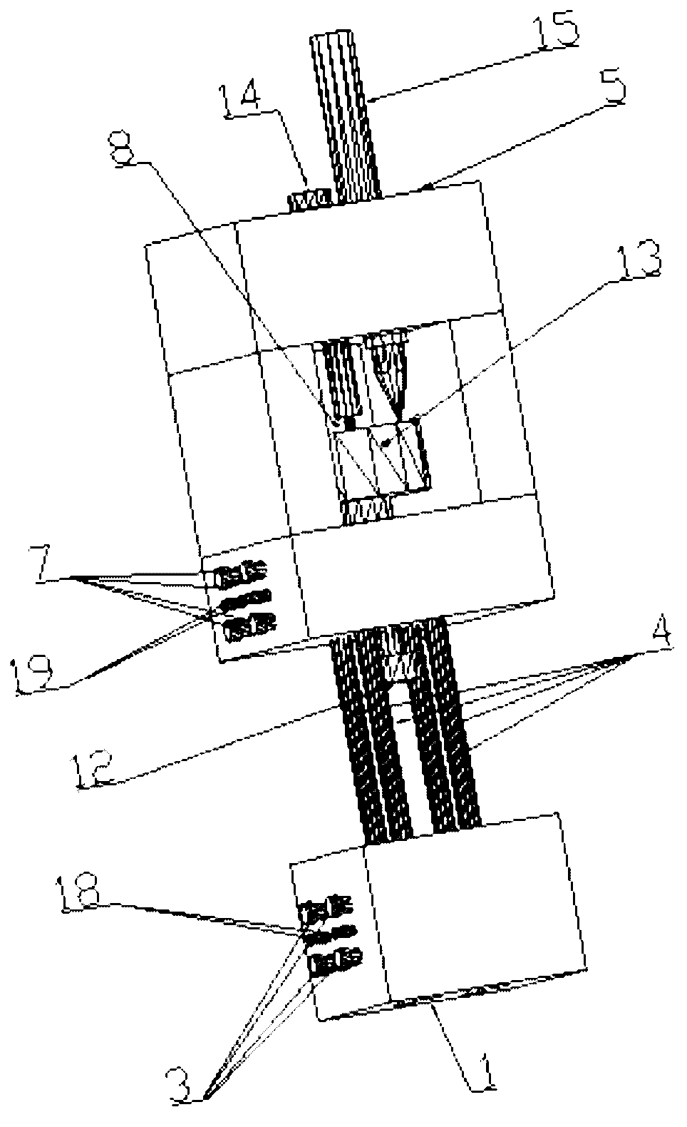
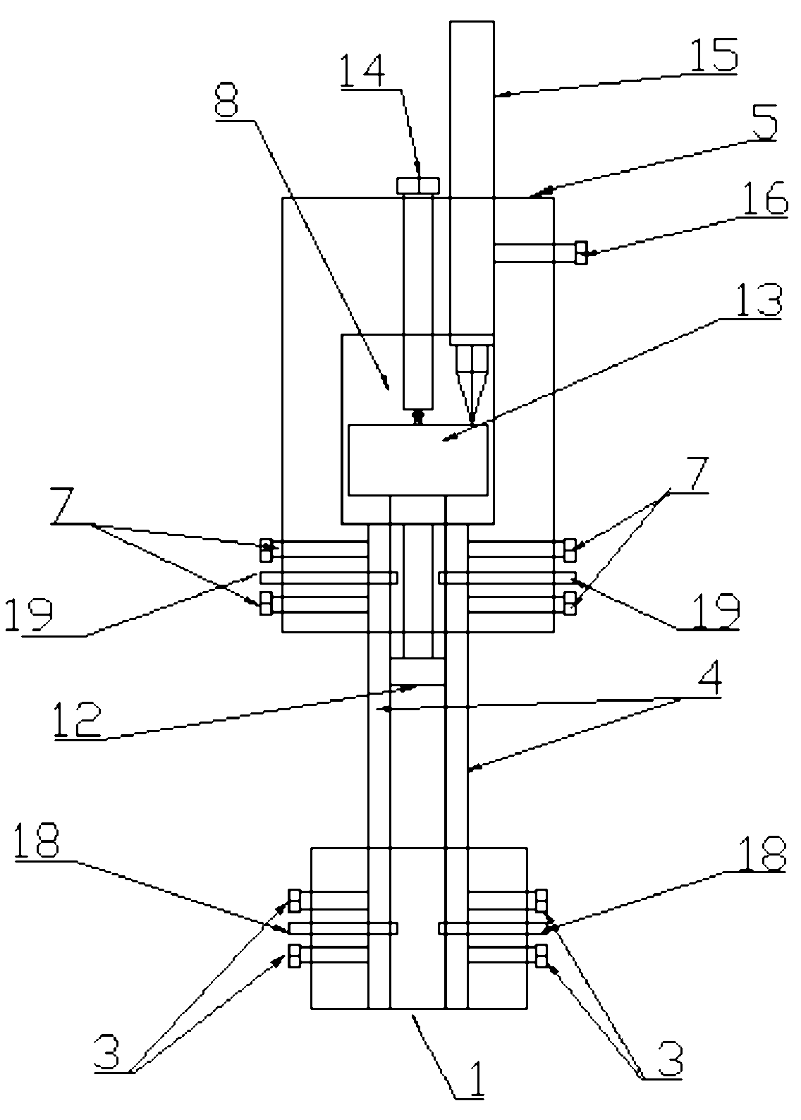
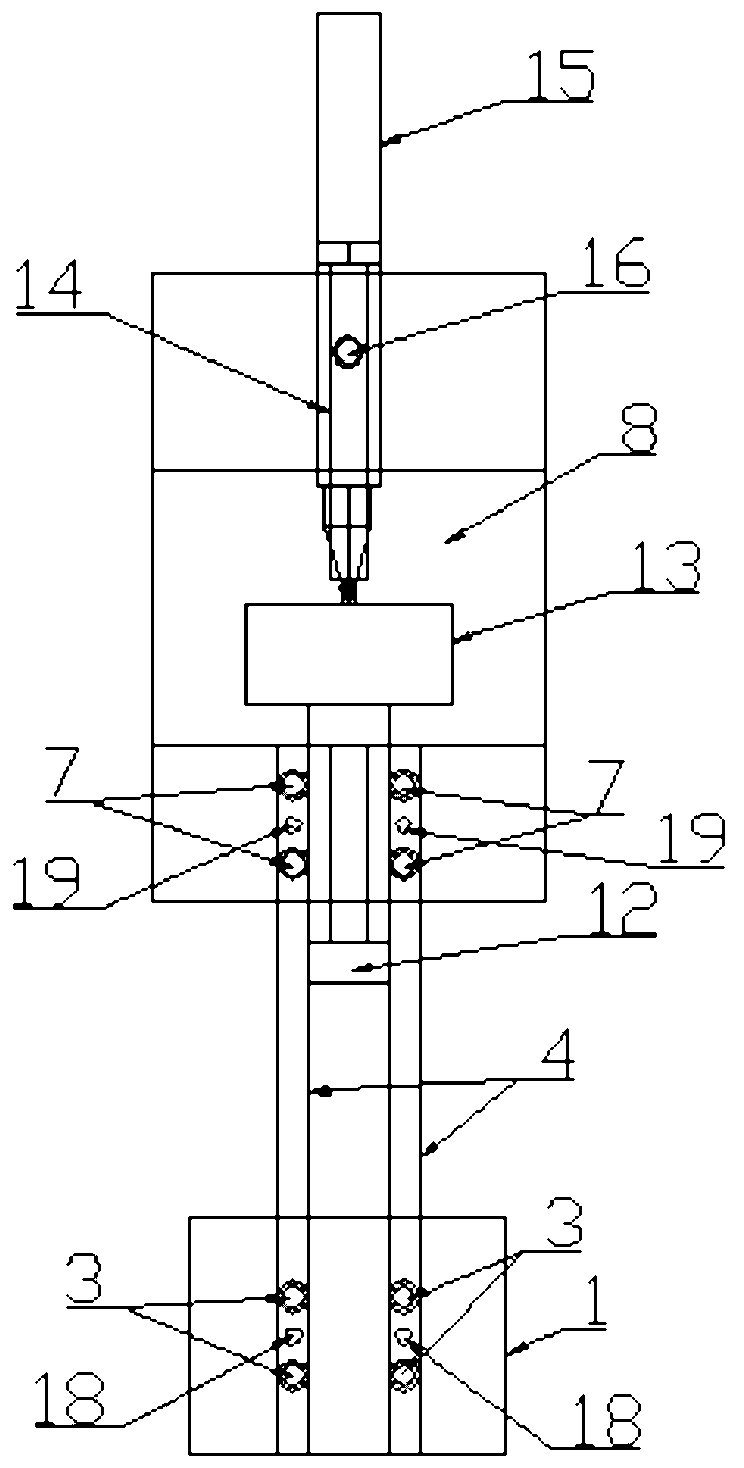
[0016] An in-situ loading device based on X-ray tomography, comprising: a lower clamping block 1, an upper clamping block 5, a displacement sensor 15 and a carbon fiber reinforced plastic rod 4, a cavity 8 is provided on the upper clamping block 5, a moving force transmission Rod 12 and loading screw 14, the moving dowel bar 12 is slidingly connected with the upper clamping block 5, and one end of the moving dowel bar 12 is located outside the upper clamping block 5, and the other end of the moving dowel bar 12 is located in the cavity In the body 8, the loading screw 14 is threadedly connected with the upper clamping block 5, a stress sensor 13 is arranged in the cavity 8 and the stress sensor 13 is located between the other end of the moving dowel 12 and the loading screw 14, the described The displacement sensing head of displacement sensor 15 conflicts with stress sensor 13;

[0017] The upper clamping block 5 is provided with an upper end connection hole 111, the upper en...


PUM


Abstract

The invention relates to an X-ray tomography-based in-situ loading device, which comprises a lower clamping block, an upper clamping block, a displacement sensor and carbon-fiber reinforced plastic rods, wherein a cavity, a moving dowel bar and a loading screw are arranged on the upper clamping block; the moving dowel bar is glidingly connected with the upper clamping block, one end of the movingdowel bar is positioning outside the upper clamping block, and the other end of the moving dowel bar is positioned in the cavity; the loading screw is in threaded connection with the upper clamping block; a stress sensor is arranged in the cavity, and a displacement sensing head of the displacement sensor is propped against the stress sensor at the part where the stress sensor is positioned between the other end of the moving dowel bar and the loading screw; upper-end connection holes and lower-end connection holes are respectively arranged on the upper clamping block and the lower clamping block; the upper and the lower ends of the carbon-fiber reinforced plastic rods are arranged in the upper-end connection holes and the lower-end connection holes and are fastened through upper-end fastening blots and a lower-end fastening blots which are respectively arranged on the upper clamping block and the lower clamping block; and upper-end fixing pins and lower-end fixing pins are respectively arranged on the upper clamping block and the lower clamping block and radially penetrate through the carbon-fiber reinforced plastic rods.

Description

Technical field: [0001] The invention belongs to mechanical devices, in particular to an in-situ loading device based on X-ray tomography. Background technique: [0002] Tomography is a calculation method for inverting physical models from observational data. Complex mathematical calculations are used in the inversion transformation. Because this transformation can only be done by computer, it is generally called computer tomography. X-ray tomography is the use of X-rays to penetrate various materials and be partially absorbed, and the ray intensity signals obtained by the detector are processed and calculated by a computer to obtain a tomographic image. X-ray tomography has the advantages of in-situ observation, tomographic imaging, and three-dimensional perspective, so it has a bright application prospect in the field of material three-dimensional microstructure characterization. With the in-depth study of damage and defect structure, researchers need to know the law of d...

Claims


Application Information

Patent Timeline
Patent Type & Authority Applications(China)
IPC IPC(8): G01N23/04G01N23/06
Inventor 薛晓波万克树
Owner SOUTHEAST UNIV
Learn More