
Three-dimensional measurement method for triple-frequency color fringe projection

A color fringe and three-dimensional measurement technology, applied in the field of optical detection, can solve problems such as low reliability, ripple phenomenon of phase results, and no consideration of spectrum aliasing, so as to improve reliability, solve instability, and realize distortion-free color resolution Coupling effect

Active Publication Date: 2013-04-17
XIAN CHISHINE OPTOELECTRONICS TECH CO LTD
View PDF10 Cites 0 Cited by
  • Summary
  • Abstract
  • Description
  • Claims
  • Application Information

AI Technical Summary

Problems solved by technology

Digital projectors are used for color three-step phase-shift fringe projection. With the help of rotating color wheel, the three-frame phase-shift fringe image can be quickly switched to avoid the problem of color coupling. However, this method has two main shortcomings: one is that it is affected by the rotation Due to the speed limit, it is difficult to measure high-speed moving objects; the second is that the phase expansion is carried out in the airspace, and the algorithm is complex and the reliability is low
The deformed fringe image to be analyzed is a two-dimensional image, and the one-dimensional processing method ignores the correlation of local pixels in all directions, so the processing effect is poor
For example, a large error will appear in the area where the height of the object changes sharply, and the error will expand along the processing method (see the literature Figure 7 , the edge of the stone face and the edge of the facial features have a large lateral expansion error)
[0006] 2) The one-dimensional EMD color decoupling algorithm (see Section 2.2.2 of this document) only considers the removal of color crosstalk of other carrier frequency components, but does not consider the spectrum aliasing problem caused by background light intensity changes, resulting in phase solution accuracy decline
At the same time, since the one-dimensional EMD decomposition method cannot use the gray information of the two-dimensional image, the extraction of the extreme points is easily disturbed by noise, resulting in serious errors (see the literature Figure 5 , the separated three stripe components have obvious pulling lines on the edge of the stone statue of the face)
[0007] 3) The one-dimensional signal processing method of the Hilbert transform number is not suitable for two-dimensional deformed fringes, and the inherent high-order harmonic aliasing of the fringes leads to obvious ripples in the phase results (see the literature Figure 7 (c))
[0008] Therefore, the method proposed by Zhou et al. in the literature has obvious flaws and does not give the measurement results of dynamic objects

Method used


Image

  • Three-dimensional measurement method for triple-frequency color fringe projection
  • Three-dimensional measurement method for triple-frequency color fringe projection
  • Three-dimensional measurement method for triple-frequency color fringe projection

Examples


Embodiment

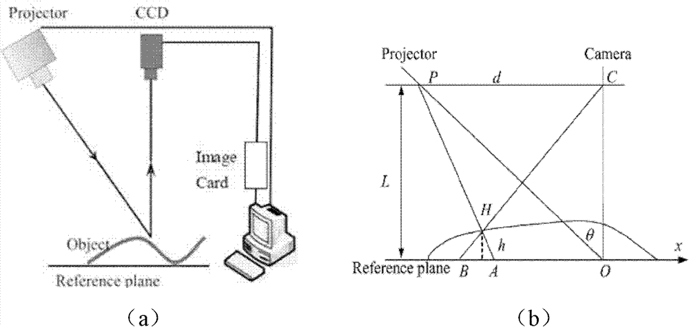
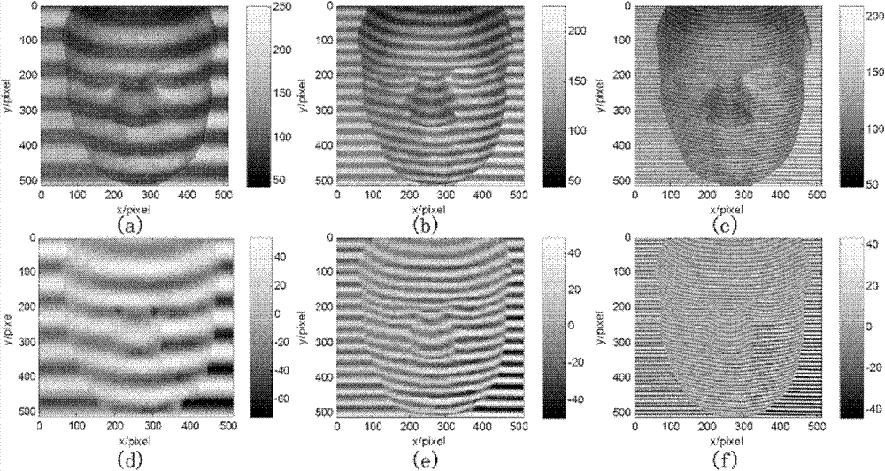
[0117] In order to analyze the measurement accuracy of the inventive method, under static conditions, with a face plaster image (such as Figure 5 Shown in (a)) as the measurement object, compare this method (such as Figure 5 (b)) with the four-step phase-shift method (such as Figure 5 (d)), the measurement results of traditional FTP (such as Figure 5 (c)). Experimental device such as figure 1 As shown, use a liquid crystal projector with a resolution of 1024×768 pixels to project a three-frequency color sinusoidal fringe pattern (the pixel periods of R, G, and B stripes are 81pixels, 27pixels, and 9pixels respectively) onto the surface of the object. figure 2 The tri-frequency color anamorphic fringe image of 512×512pixels captured by CCD is shown.

[0118] The method proposed by the present invention is used to process the three-frequency color deformation fringe image. In order to better illustrate the method, a more detailed intermediate result is given. Each car...


PUM


Abstract

The invention discloses a three-dimensional measurement method for triple-frequency color fringe projection, and the method comprises the following steps: enabling a computer to generate a color fringe pattern; projecting the color fringe pattern onto a tested object plane by virtue of a digital projector; shooting a deformed color fringe pattern at the other angle by a color CCD (Charge Coupled Device); subtracting a color channel containing high-frequency fringes and a color channel containing immediate-frequency fringes to obtain a high-frequency and low-frequency compound fringe pattern; subsequently, decomposing, and separating high-frequency components from immediate-frequency components; similarly, subtracting color channels containing immediate-frequency components and low-frequency components; decomposing to obtain immediate-frequency carrier components from low-frequency carrier components; covering phases by each high-frequency, immediate-frequency and low-frequency frequency carrier component transformed and demodulated by two-dimensional short-time Fourier transform; successively unfolding the covered phases according to the immediate-frequency carrier components and the low-frequency carrier components to obtain the unfolded phase of a high-frequency carrier frequency item; and unfolding the phase to restore the height of the object. The measurement method adoptsa triple-frequency color fringe projection technology to form a full-field measurement technology based on single-frame shooting, and the full-field three-dimensional outline measurement of a dynamicobject is quickly realized.

Description

technical field [0001] The invention belongs to the field of optical detection, and relates to an optical detection method of a three-dimensional profile, in particular to a three-dimensional measurement method of three-frequency color fringe projection. Background technique [0002] The three-dimensional measurement of dynamic objects has broad application prospects in many fields such as industrial production, national defense security, medical research, and life entertainment, such as online inspection of product quality, medical repair surgery, face recognition, digital media, etc. [0003] In order to achieve fast and accurate three-dimensional measurement of dynamic objects, the stereo vision method of multi-camera shooting and the structured light method of fringe projection are usually used. Stereo vision technology has low measurement accuracy due to the uncertainty of stereo matching, and multiple cameras also increase hardware costs. At present, the fringe projec...

Claims


Application Information

Patent Timeline
Patent Type & Authority Patents(China)
IPC IPC(8): G01B11/25
Inventor 周翔赵宏邹海华杨涛刘锐刘振军
Owner XIAN CHISHINE OPTOELECTRONICS TECH CO LTD
Learn More