
Construction method for formed steel reinforced concrete beam-column nodes

A beam-column joint, concrete structure technology, applied in the direction of building, building structure, etc., to achieve the effect of reducing steel joints, reducing welding stress, and speeding up the construction progress

Inactive Publication Date: 2012-01-18
HUBEI HONGYI BUILDING DECORATION ENG
View PDF2 Cites 33 Cited by
  • Summary
  • Abstract
  • Description
  • Claims
  • Application Information

AI Technical Summary

Problems solved by technology

However, no solution has been given for how to adjust the intricate relationship between the beam horizontal reinforcement at the joint position and how to arrange the stirrup when the column stirrup intersects with the column main reinforcement and the column stiffener in the joint domain.

Method used


Image

  • Construction method for formed steel reinforced concrete beam-column nodes
  • Construction method for formed steel reinforced concrete beam-column nodes
  • Construction method for formed steel reinforced concrete beam-column nodes

Examples


Embodiment Construction

[0020] Now how the present invention is implemented in conjunction with the accompanying drawings:

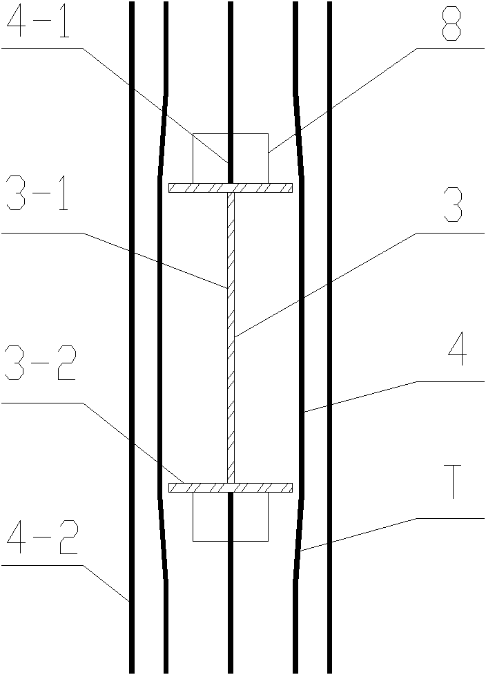
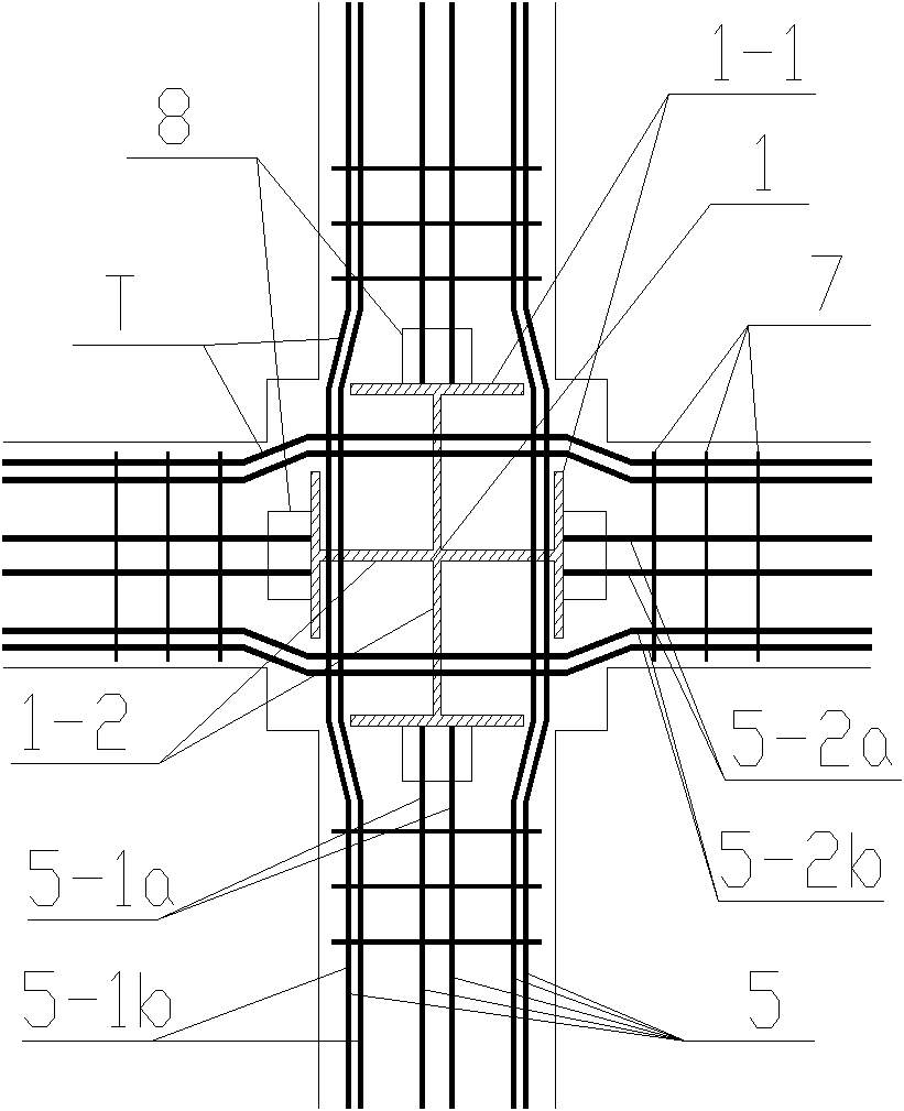
[0021] Firstly connect the shaped steel beams and shaped steel columns according to the existing technology. The shaped steel columns are composed of cross-shaped steel bone columns and H-shaped steel columns. The steel columns are composed of wing plates and web plates. The two sides are disconnected, and the shaped steel beam and the shaped steel column are connected by welding or bolts through their flanges, and stiffening plates are arranged horizontally on the upper and lower flanges of the shaped steel column corresponding to the shaped steel beam;

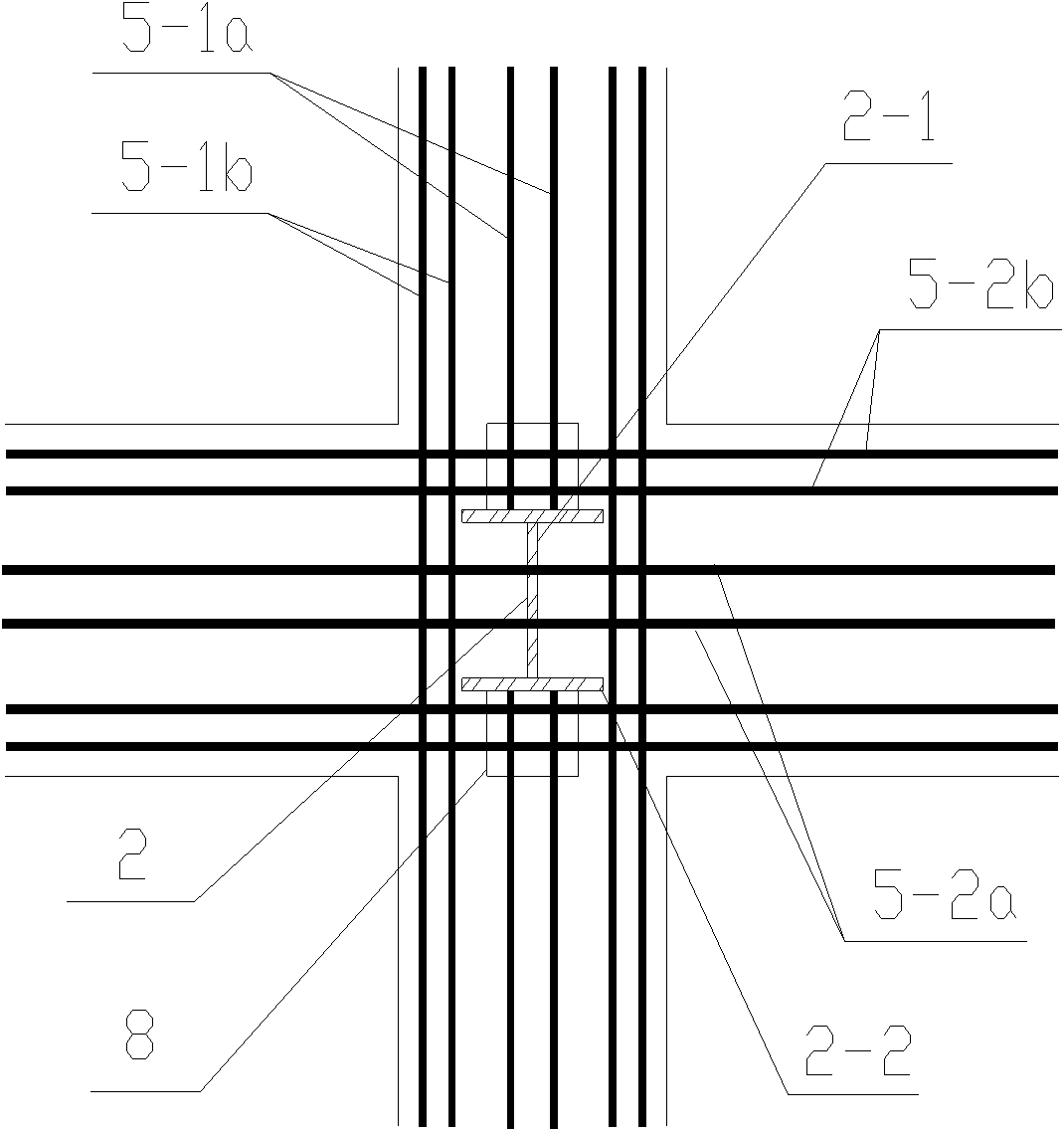
[0022] When arranging and binding the column reinforcement at the beam-column joint position, the column reinforcement is arranged first, and then the stirrup is set and bound. Among them, when the main reinforcement 4 of the column meets the shaped steel beam 3, the main reinforcement 4-1 in the middle position should be dis...


PUM


Abstract

The invention relates to a construction method for formed steel reinforced concrete beam-column nodes, belonging to the technical field of industrial and civil building construction. According to the invention, the problem for arranging and binding intricate and complicated steel bars and corresponding formed steel in formed steel beam and formed steel column connection node domains is creatively and sequentially solved; the boring of formed steel wing plates is avoided; the up-and-down adjusting and the bending for horizontal bars of X beams and Y beams can be realized through enabling the horizontal / longitudinal bars of the X beams and the Y beams to intersect with the formed steel columns and opening vertical long-strip holes on web plates of the formed steel columns; the area of the openings on the web plates of the formed steel columns is controlled to exceed 20% of that of the sectional area of the web plates, thus the negative influence on the strength of the web plates of the formed steel columns because of the openings is reduced to the maximum; and hoop bars are orderly arranged on the upper surfaces of column stiffening plates at intervals at the spatial staggered positions of column main bars, the column stiffening plates and column hoop bars, thus the number of steel bar joints is reduced. The construction method provided by the invention not only increases the construction efficiency, but also ensures to enhance the project quality and the node domain bearing capacity for the beam-column connection of formed steel reinforced concrete structures.

Description

technical field [0001] The construction method of the steel concrete beam-column joint of the invention belongs to the technical field of industrial and civil building construction. Background technique [0002] The steel-concrete composite structure is a composite structure formed by configuring steel in a reinforced concrete structure. It has the dual advantages of steel structure and concrete structure. Compared with steel structure, it saves steel and increases the rigidity of components and buildings. Compared with concrete structure, it reduces the section, reduces weight, increases the ductility of components, and It has higher strength and gives full play to the characteristics of two different materials, steel (in tension) and concrete (in compression). Therefore, it has been widely used in construction. However, in the actual construction of the steel-concrete composite structure, there will be problems in the reinforcement of the beam-column joint domain, the de...

Claims


Application Information

Patent Timeline
IPC IPC(8): E04B1/41E04B1/58
Inventor 王少重
Owner HUBEI HONGYI BUILDING DECORATION ENG
Learn More