Flying fork device

A technology of flying fork and spindle, applied in the direction of coil manufacturing, etc., can solve the problems of easy wire breakage and low winding efficiency

Active Publication Date: 2013-01-02
TANAC AUTOMATION
View PDF2 Cites 0 Cited by
  • Summary
  • Abstract
  • Description
  • Claims
  • Application Information

AI Technical Summary

Problems solved by technology

[0002] The usual winding machine fixes the skeleton on the jig, and the skeleton rotates circumferentially and moves axially with the jig to wind the wire on the skeleton to form a coil, but for extremely small coils and extremely thin windings, use this This method of winding is easy to break, and the efficiency of winding is low

Method used


Image

  • Flying fork device
  • Flying fork device
  • Flying fork device

Examples


Embodiment Construction

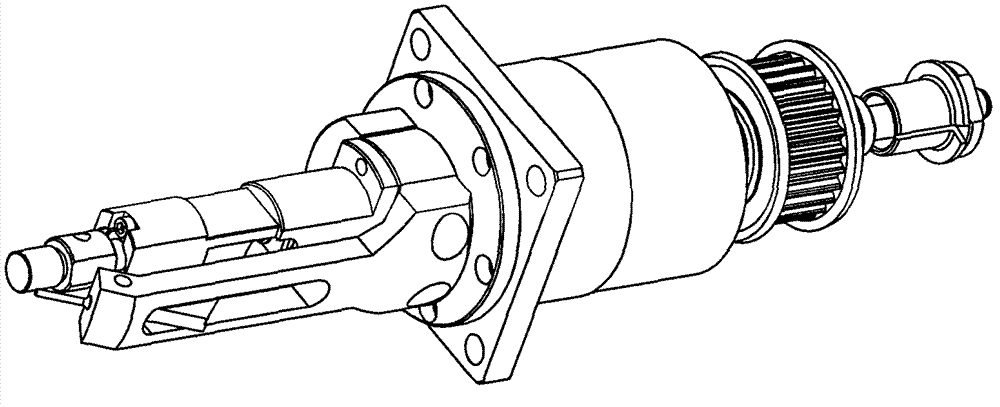
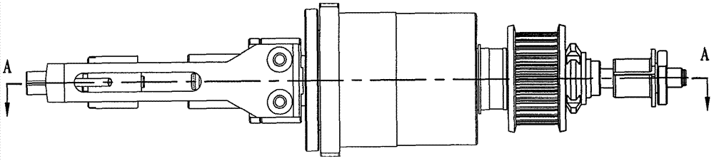
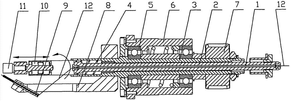
[0012] The present invention will be further described below in conjunction with the accompanying drawings and specific embodiments.

[0013] Figure 1 to Figure 3 It is a schematic diagram of the structure of the flying insertion device. It can be seen from the figure that it includes a fly fork mandrel 2 with a through hole 1 in the center. 3, the fly-fork mandrel 2 can move back and forth in the fly-fork main shaft 3 as image 3 and Figure 4 As shown, the flying fork main shaft 3 is fixed in the flying fork main shaft seat 6 through the bearing 5, the rear portion of the flying fork main shaft 3 is fixed with a synchronous pulley 7, and the flying fork main shaft 3 is fixed with a belt that rotates with the flying fork main shaft 3. The flying fork arm 8 is fixed with a tubular winding finger 9 on the flying fork arm 8 . The front end of the flying fork mandrel 2 is fixed with a top core 11 that withstands the skeleton or jig through the front bearing 10 . The winding...


PUM


Abstract

The invention discloses a flying fork device and aims to provide a flying fork device which has simple structure, reliable operation, and high loading and unloading speed and is used for realizing smaller skeleton coiling. The flying fork device comprises a flying fork spindle of which the center is provided with a through hole; the flying fork spindle is inserted in a flying fork main shaft, is ejected to the front end of the flying fork main shaft through a compression spring, and can move front and back in the flying fork main shaft; the flying fork main shaft is fixed in a flying fork main shaft seat; a synchronous belt wheel is fixed at the rear part of the flying fork main shaft; a flying fork arm which rotates together with the flying fork main shaft is fixed on the flying fork main shaft; and a tubular coiling finger is fixed on the flying fork arm. The device provided by the invention has the advantages that a jig can realize the rapid and accurate positioning in circumferential and axial directions of the main shaft, the difficulty in small skeleton coiling is solved and the loading and unloading of the jig on an automatic coiling machine is very convenient and flexible.

Description

technical field [0001] The invention relates to a type of work on an automatic winding machine, and more particularly relates to a flying fork device for winding smaller frames on the automatic winding machine. Background technique [0002] The usual winding machine fixes the skeleton on the jig, and the skeleton rotates circumferentially and moves axially with the jig to wind the wire on the skeleton to form a coil, but for extremely small coils and extremely thin windings, use this This method of winding is easy to break, and the efficiency of winding is low. With the continuous improvement of winding machine automation technology today, the stability of the clamping structure on the automatic clamping device also needs to be continuously improved, and the shape of the skeleton is also varied. The market urgently needs a simple and stable clamping structure. Winding device. Contents of the invention [0003] The object of the present invention is to provide a flying fo...

Claims


Application Information

Patent Timeline
Patent Type & Authority Patents(China)
IPC IPC(8): H01F41/06
Inventor 钱承林
Owner TANAC AUTOMATION
Why Eureka
Try Eureka