


Quick Research
Generate reliable direction feasibility study reports for your R&D in just a few steps.

Technical Q&A
Discover and master advanced knowledge NOW. Basics, ideas, possibilities, all at once.

Find Solutions
As an expert in R&D theories, this can generate solutions to your technical problems instantly.

Evaluate Feasibility
Analyze your overall solution with one click, know your potential R&D risks in advance.

Monitor Landscape
Get weekly tech updates, stay abreast of the latest tech innovations and key insights.
Two-stage smoke-gas-air heat-exchanger system applied to thermal power plant
A flue gas heat exchanger and air heat exchanger technology, applied in lighting and heating equipment, combustion methods, indirect carbon dioxide emission reduction and other directions, can solve problems such as reducing steam turbine exhaust parameters, single function, and increasing unit construction and maintenance costs.
- Summary
- Abstract
- Description
- Claims
- Application Information
AI Technical Summary
Problems solved by technology
Method used
Image

Examples
Embodiment 1
[0135] Embodiment 1 (corresponding to the schematic diagram attached image 3 , attached Figure 4 , image 3 for direct heat exchangers, Figure 4 for indirect heat exchangers)
[0136] After the flue gas produced by the combustion of the boiler 100 passes through the air preheater 2, its temperature is generally between 110°C and 170°C according to the type of the boiler and the type of coal fired. After the flue gas passes through the first-stage flue gas-air heat exchanger 31, the temperature drops to about 10°C above the acid dew point temperature of the flue gas. The first-stage flue gas-air heat exchanger 31 uses the air entering the boiler to absorb the temperature of the flue gas. The flue gas comes from the boiler flue gas at the outlet of the air preheater, and the air comes from the cold air at the outlet of the second-stage flue gas-air heat exchanger 32 . After the flue gas passes through the first-stage flue gas-air heat exchanger 31, it enters the flue gas...
Embodiment 2
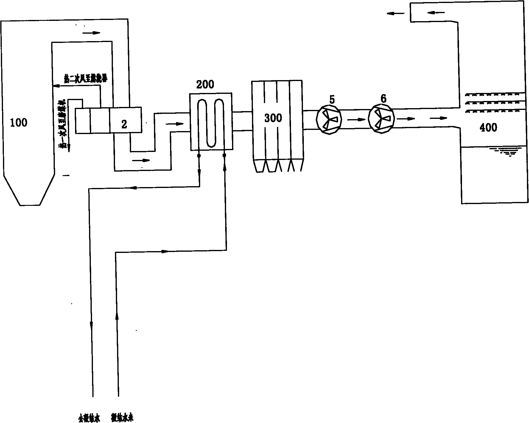
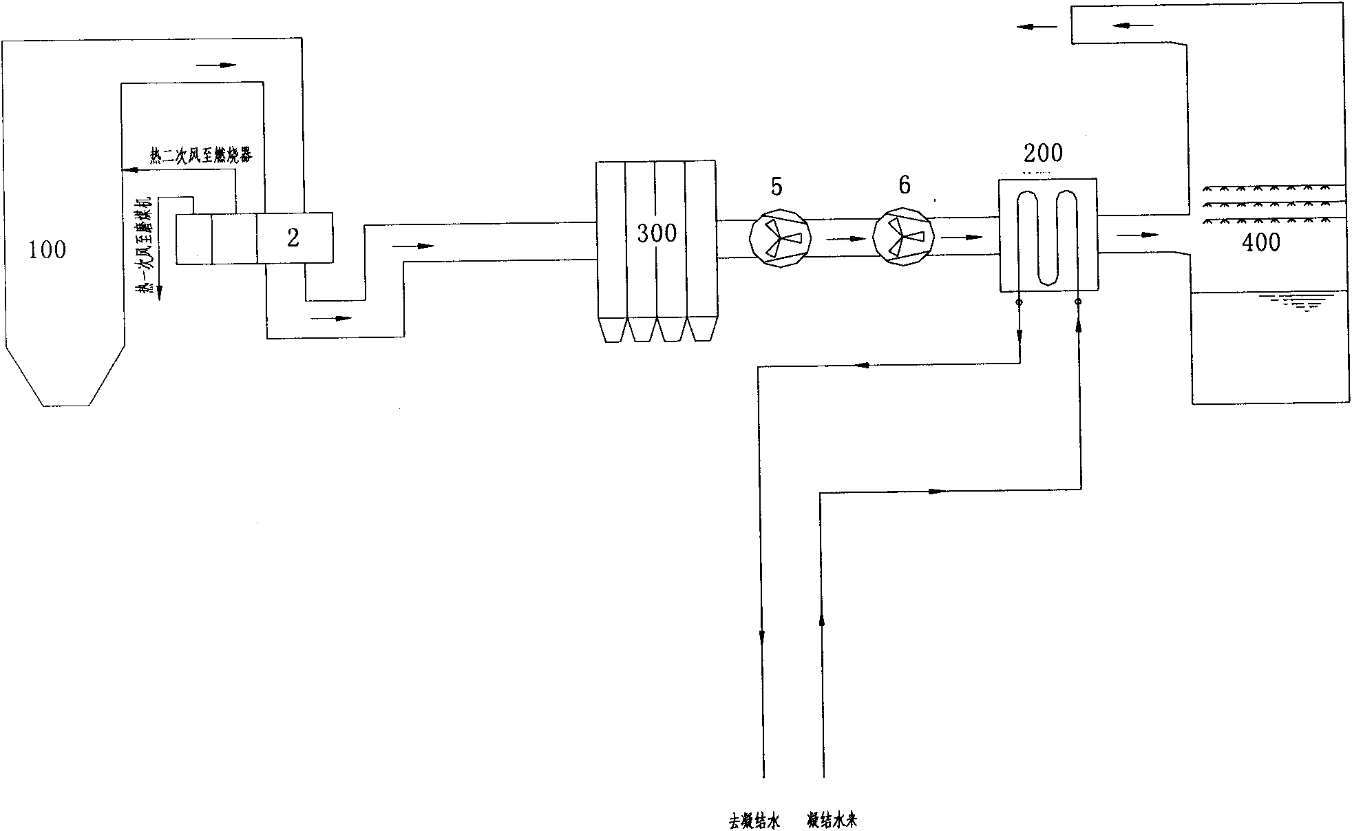
[0139] Embodiment 2 (corresponding to the schematic diagram attached Figure 5 , attached Image 6 , Figure 5 for direct heat exchangers, Image 6 for indirect heat exchangers)
[0140] After the flue gas generated by the combustion of the boiler passes through the air preheater 2, its temperature is generally between 110°C and 170°C according to the type of the boiler and the type of coal fired. After the flue gas passes through the first-stage flue gas-water heat exchanger 31, the temperature drops to about 10°C above the acid dew point temperature of the flue gas. The flue gas comes from the boiler flue gas at the outlet of the air preheater 2, and the water source can be the condensed water in the condensate water system of the steam turbine, that is, from the outlet of a certain stage of low-pressure heater 7 or the outlet of several stages of low-pressure heaters and aggregated, the condensed water After absorbing heat through the first-stage flue gas-water heat exc...
Embodiment 3
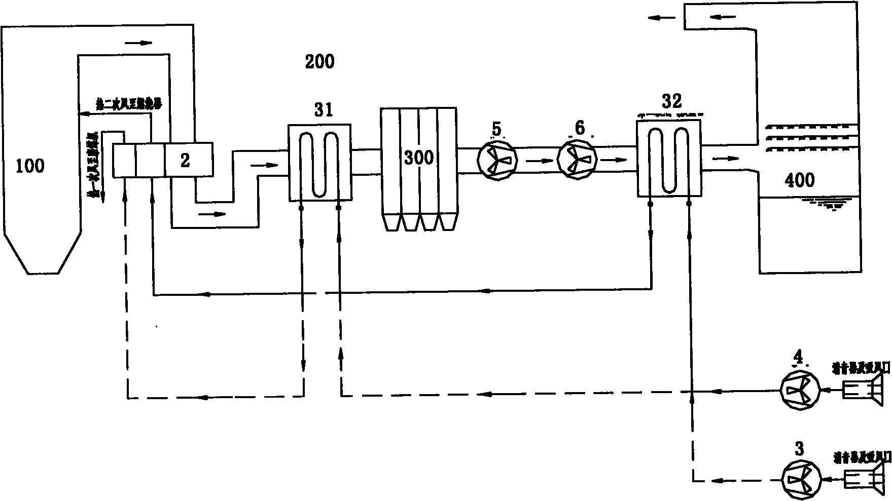
[0143] Embodiment 3 (corresponding to the schematic diagram attached Figure 7 , attached Figure 8 , Figure 7 for direct heat exchangers, Figure 8 for indirect heat exchangers)
[0144] After the flue gas produced by the combustion of the boiler 100 passes through the air preheater 2, its temperature is generally between 110°C and 170°C according to the type of the boiler and the type of coal fired. After the flue gas passes through the first-stage flue gas-air heat exchanger 31, the temperature drops to about 10°C above the acid dew point temperature of the flue gas. The first-stage flue gas-air heat exchanger 31 uses the air entering the boiler to absorb the temperature of the flue gas. The flue gas comes from the boiler flue gas at the outlet of the air preheater, the air comes from the cold secondary air at the outlet of the blower, and the cold primary air at the outlet of the primary fan can also be used. After the flue gas passes through the first-stage flue gas...
PUM
 Abstract
Description
Claims
Application Information
 - R&D Engineer
- R&D Manager
- IP Professional
- Industry Leading Data Capabilities
- Powerful AI technology
- Patent DNA Extraction
Browse by: Latest US Patents, China's latest patents, Technical Efficacy Thesaurus, Application Domain, Technology Topic, Popular Technical Reports.
© 2024 PatSnap. All rights reserved.Legal|Privacy policy|Modern Slavery Act Transparency Statement|Sitemap|About US| Contact US: help@patsnap.com