Wire-brush-type differential fusant electrostatic spinning device and method

A melt electrospinning and wire brush technology, which is applied in textiles and papermaking, filament/thread forming, fiber processing, etc., can solve the problems of reducing spinning reliability, increasing cost, and complex structure, etc., to achieve large-scale Scale industrialization, reduce manufacturing and installation costs, and benefit the effect of melt viscosity

Active Publication Date: 2014-01-08
BEIJING UNIV OF CHEM TECH
View PDF9 Cites 0 Cited by
  • Summary
  • Abstract
  • Description
  • Claims
  • Application Information

AI Technical Summary

Problems solved by technology

[0004] U.S. patents US006616435 and US20080241297 mentioned a device for the industrial production of non-woven ultrafine fibers by using multiple nozzles or spinnerets by electrospinning. This patent mainly proposes specific solutions and devices for the production of non-woven materials by the solution electrostatic method. The structure is complex; for solution electrospinning, Stanislav Petrik et al. of the Czech Republic proposed a nozzle-free electrospinning method for direct electrospinning on the free liquid surface, which realized the mass production of small-scale solution electrospinning, while for melt electrospinning, there is no nozzle. Due to the high limit voltage value of direct electrospinning on the free melt surface, it will break down the air and discharge before the spinning voltage is reached, so it is difficult to realize
At present, the batch equipment for melt electrospinning mainly focuses on the application of multiple nozzles and simple arrangement and integration. The manufacture and installation of hundreds of nozzles not only increases the cost, but also reduces the spinning reliability.

Method used


Image

  • Wire-brush-type differential fusant electrostatic spinning device and method
  • Wire-brush-type differential fusant electrostatic spinning device and method
  • Wire-brush-type differential fusant electrostatic spinning device and method

Examples


Embodiment Construction

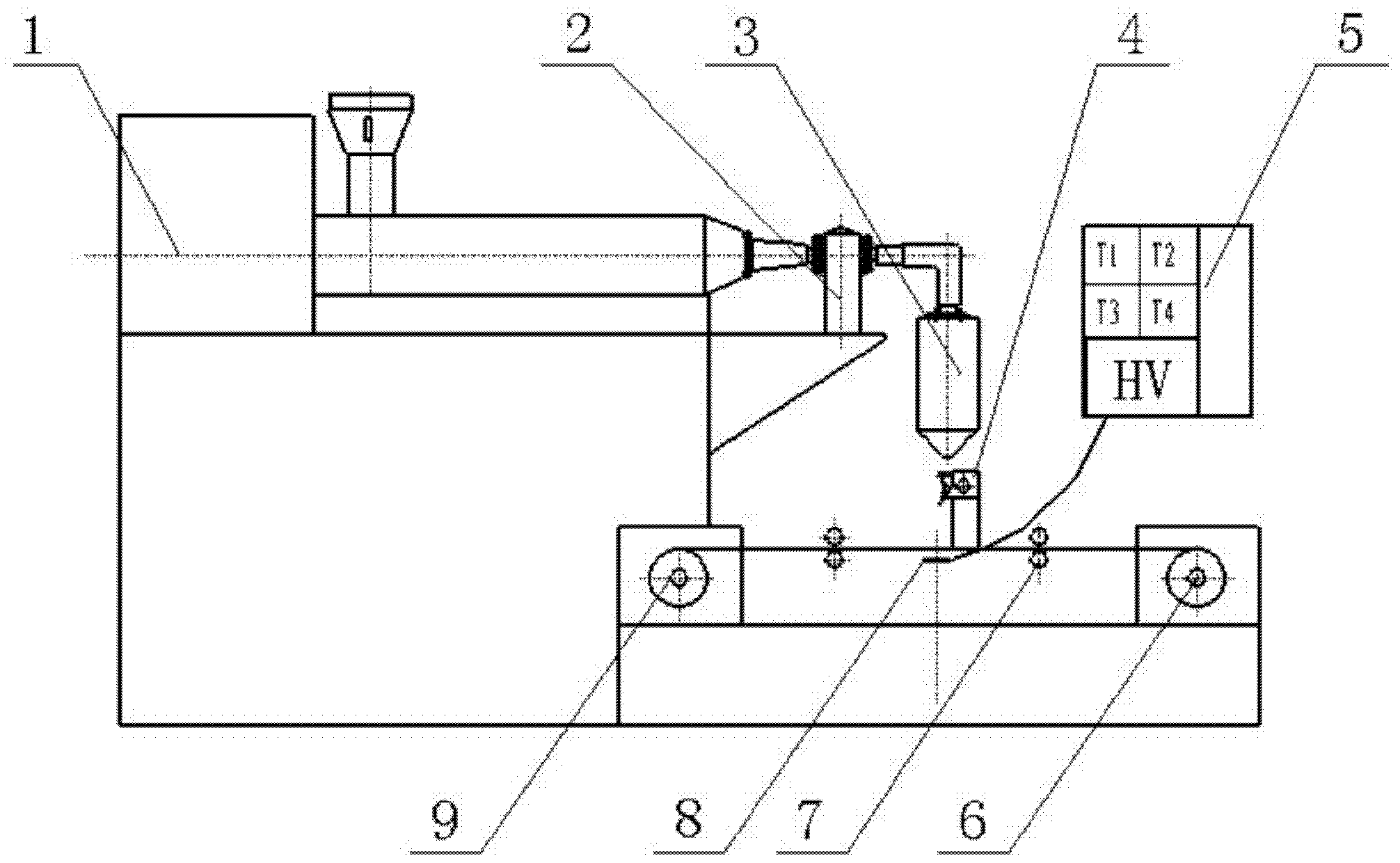
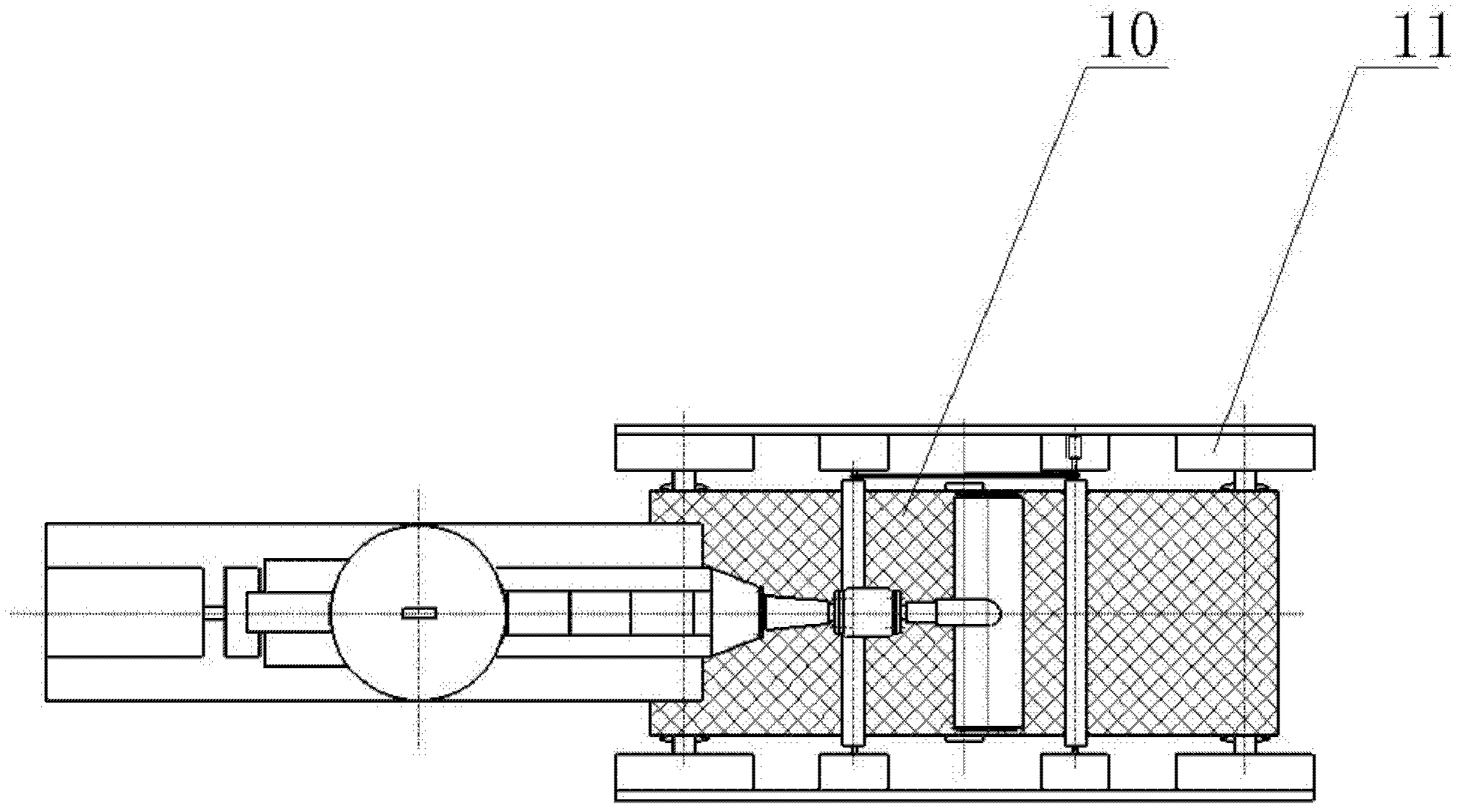
[0022] A silk brush type differential melt electrospinning device of the present invention, such as figure 1 As shown in ~5, it mainly includes a melt delivery device 1, a melt metering pump 2, an extruder head 3, a differential wire brush 4, a control system 5, a collection device 11, and a DC high-voltage electrode 8, wherein the melt delivery device 1 and The melt metering pump 2 inlet is connected, the melt metering pump 2 outlet is connected to the extruder head 3, the differential wire brush 4 is placed between the extruder head 3 and the collection device 11, and the DC high voltage electrode 8 of the high voltage electrostatic device is installed on the collector Under the base cloth 10 of the device 11, the extruder head 3 and the differential wire brush 4 are respectively grounded.

[0023] The present invention is a wire brush type differential melt electrospinning device, in which the differential wire brush 4 is grounded, wherein the collection net of the collecti...


PUM


Abstract

The invention discloses a filament-brush-type differential fusant electrostatic spinning device and a method. The device comprises a fusant conveying device, a fusant metering pump, an extruder head, a differential silk brush, a control system, a collection device and a high-voltage electrode device. The fusant outlet of the fusant conveying device is connected with the fusant inlet of the fusant metering pump. The fusant outlet of the fusant metering pump is connected with the extruder head. The differential filament brush is arranged between the extruder head and the collection device. The direct-current high-voltage electrode of a high-voltage electrostatic device is arranged at a position right below the base cloth of the differential filament brush. The differential filament brush consists of a thin metal sheet and saw teeth or filaments which are arranged at adjacent intervals. The saw teeth or the filaments are arranged in a single row or in a plurality rows in a staggering way. By introducing the differential filament brush, the spinning efficiency is greatly improved and the manufacturing and installation cost is reduced; and by controlling the temperature of the differential filament brush, the reduction of fusant viscosity is facilitated, the degradation is reduced, the traditional method of using a plurality of spray nozzles or capillary modules to improve electrostatic spinning efficiency is changed and the large-scale industrialization of electrostatic spinning is expected to be realized.

Description

technical field [0001] The invention relates to a large-batch melt electrostatic spinning method and device, belonging to the field of electrostatic spinning. Background technique [0002] Electrospinning is also called electrospinning. As early as 1930, the US patent US1975504 had reported the electrospinning method. In 1993, this technology was defined as electrospinning technology. The electrospinning process is to apply a high-voltage electric field between the nozzle and the receiving device at the supply end of the solution or melt, so that the charged solution or polarized melt forms a Taylor cone under the action of the electric field force, and then overcomes the surface tension to form a jet. , then sharply thins during the movement, and finally obtains the process of microfibers on the receiving device. [0003] Compared with solution electrospinning, melt electrospinning has the advantages of no solvent recovery, high safety, high spinning efficiency, and good m...

Claims


Application Information

Patent Timeline
Patent Type & Authority Patents(China)
IPC IPC(8): D01D5/00D01D5/42
Inventor 杨卫民李好义丁玉梅何雪涛
Owner BEIJING UNIV OF CHEM TECH
Why Eureka
Try Eureka