Multi-view image encoding method, multi-view image decoding method, multi-view image encoding device, multi-view image decoding device, multi-view image encoding program, and multi-view image decoding program

A technology of multi-view image and encoding method, applied in the fields of multi-view image encoding, multi-view image decoding, multi-view image encoding device, multi-view image decoding device, multi-view image encoding program and multi-view image decoding program , which can solve the problem of coding efficiency degradation, and achieve the effect of reducing the prediction difference and reducing the amount of code.

Active Publication Date: 2012-01-04
NIPPON TELEGRAPH & TELEPHONE CORP
View PDF5 Cites 4 Cited by
  • Summary
  • Abstract
  • Description
  • Claims
  • Application Information

AI Technical Summary

Problems solved by technology

[0009] In parallax compensation prediction and view synthesis prediction, when there are individual differences in the response of the imaging elements of the cameras, or when gain control and gamma correction are performed for each camera, or subject depth, aperture, etc. for each camera Coding efficiency degrades when the settings of different settings are different, or when there are direction-dependent lighting effects in the scene

Method used


Image

  • Multi-view image encoding method, multi-view image decoding method, multi-view image encoding device, multi-view image decoding device, multi-view image encoding program, and multi-view image decoding program
  • Multi-view image encoding method, multi-view image decoding method, multi-view image encoding device, multi-view image decoding device, multi-view image encoding program, and multi-view image decoding program
  • Multi-view image encoding method, multi-view image decoding method, multi-view image encoding device, multi-view image decoding device, multi-view image encoding program, and multi-view image decoding program

Examples


Embodiment Construction

[0059] Hereinafter, the present invention will be described in detail with reference to the drawings showing embodiments of the present invention.

[0060] Furthermore, in the following description, by adding information that can specify a position to the video (frame) (the information enclosed by marks [] is a coordinate value or an index that can be associated with the coordinate value), so that the position can be passed The pixels represent the video signal being sampled.

[0061] [1] Multi-view video encoding device according to the first embodiment of the present invention

[0062] figure 1 The device configuration of the multi-view video encoding device 100 according to the first embodiment of the present invention is shown.

[0063] like figure 1 As shown, the multi-view video encoding device 100 of Embodiment 1 includes: an encoding target image input unit 101, an encoding target image memory 102, a reference camera image input unit 103, a reference camera image ...


PUM


Abstract

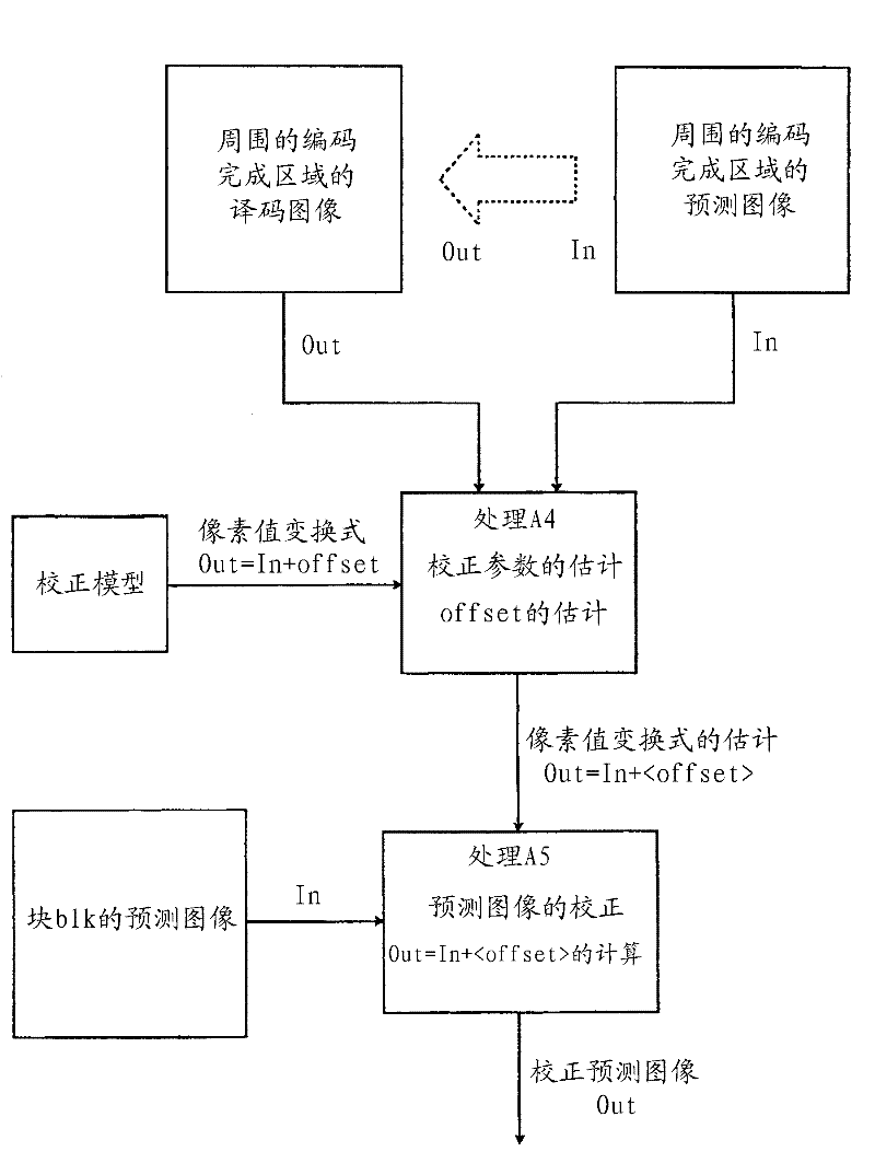
In the disclosed multi-view image encoding / decoding method in which a frame to be encoded / decoded is divided and encoding / decoding is done to each region, first, a prediction image is generated not only for the region to be processed, but also for the already encoded / decoded regions neighboring to the region to be processed. The prediction image is generated using the same prediction method for both kinds of regions. Next, correction parameters for correcting illumination and color mismatches are estimated from the prediction image and decoded image of the neighboring regions. At this time, the estimated correction parameters can be obtained even at the decoding side, therefore, encoding them is unnecessary. Thus, by using the estimated correction parameters to correct the predicted image that was generated for the region to be processed, a corrected predicted image that can be actually used is generated.

Description

technical field [0001] The present invention relates to a multi-viewpoint image encoding method and device for encoding an image of a certain subject captured by a plurality of cameras, and a multi-viewpoint image for decoding code data encoded by the multi-viewpoint image encoding method A decoding method and device thereof, a multi-viewpoint image coding program for realizing the multi-viewpoint image coding method, and a multi-viewpoint image decoding program for realizing the multi-viewpoint image decoding method. [0002] This application claims priority based on Japanese Patent Application No. 2009-29249 for which it applied in Japan on February 12, 2009, and uses the content here. Background technique [0003] A multi-viewpoint image refers to a plurality of images captured by multiple cameras on the same subject and background, and a multi-viewpoint moving image (multi-viewpoint video) is a moving image thereof. [0004] Motion compensation prediction and parallax c...

Claims


Application Information

Patent Timeline
Patent Type & Authority Applications(China)
IPC IPC(8): H04N7/32
CPCH04N19/00769H04N19/80H04N13/00H04N19/597
Inventor 志水信哉木全英明
Owner NIPPON TELEGRAPH & TELEPHONE CORP
Why Eureka
Try Eureka