Optical connector
A technology of optical connectors and connecting mechanisms, applied in the direction of instruments, optics, light guides, etc., can solve the problems of cumbersome formation of the end face of the optical fiber and defects of the optical fiber 2 and 10a, and achieve the effect of simplifying assembly and reducing defects
- Summary
- Abstract
- Description
- Claims
- Application Information
AI Technical Summary
Problems solved by technology
Method used
Image

Examples
Embodiment 1
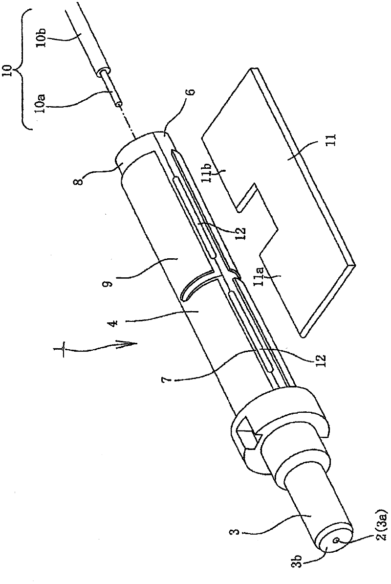
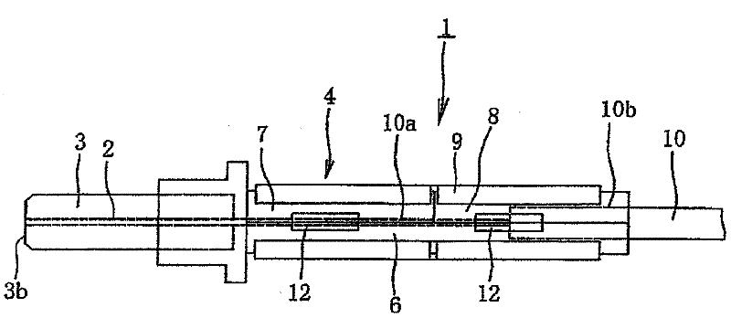
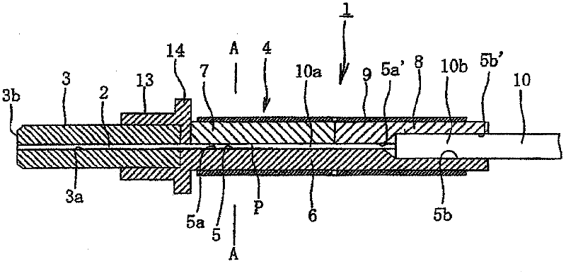
[0073] figure 1 It is a perspective view showing the appearance of the optical connector 1 according to Embodiment 1 of the present invention together with opening and closing members, figure 2 yes figure 1 side view of the optical connector 1, image 3 It is a longitudinal sectional view of the optical connector 1 .
[0074] This optical connector 1 is provided with: ferrule 3, and it is provided with built-in optical fiber (cladding is removed the bare optical fiber) 2, and ferrule 3 is implemented end face grinding; The opposite side is extended. The built-in optical fiber 2 is butt-connected to the bare optical fiber 10 a inserted into the optical fiber 10 .
[0075] Both the built-in optical fiber 2 and the bare optical fiber 10a inserted into the optical fiber are silica optical fibers with a diameter of 125 μm.
[0076] The connection mechanism 4 consists of a base body 6 formed with a positioning groove 5 continuous with the fiber hole 3a of the ferrule 3, a cove...
Embodiment 2
[0104] Below, combine Figure 8A ~ Figure 10B , the optical connector 1 according to the second embodiment will be described. The description of the same parts as in Example 1 will be omitted, and the description will focus on different parts.
[0105] The present embodiment 2 has the above-mentioned and Figure 1 to Figure 5 The structure is the same, and its description is omitted here. In embodiment 2 of the present invention, such as Figure 8A as well as Figure 8B As shown in the enlarged figure, the end face 2a of the rear end side of the built-in optical fiber 2 that abuts with the inserted optical fiber 10 is formed into an inclined end face 2a by cutting processing, and the above-mentioned inclined end face 2a of the built-in optical fiber 2 is subjected to discharge treatment using a thermal splicer, thereby The edge rounding of the inclined end face 2a is mainly performed. The rounded peripheral edge is indicated by reference numeral 2b. Likewise, the inserti...
Embodiment 3
[0126] Below, combine Figure 11A ~ Figure 12C , the optical connector according to the third embodiment will be described. The description of the same parts as in Embodiment 1 will be omitted, and the description will focus on different parts.
[0127] In Embodiment 1, although the refractive index matching agent is filled between the end faces of the two optical fibers, in this Embodiment 3, as will be described later, there are cases where it is necessary to fill the refractive index matching agent between the end faces of the two optical fibers, and There is no need to fill the refractive index matching agent between the end faces of the two optical fibers.
[0128] The present embodiment 3 has the above-mentioned and Figure 1 to Figure 5 The structure is the same, and the explanation is omitted here. In embodiment 3 of the present invention, as Figure 11A as well as Figure 11B As shown in the enlarged figure, the end face 2a on the rear end side of the built-in op...
PUM
 Abstract
Description
Claims
Application Information
 - Generate Ideas
- Intellectual Property
- Life Sciences
- Materials
- Tech Scout
- Unparalleled Data Quality
- Higher Quality Content
- 60% Fewer Hallucinations
Browse by: Latest US Patents, China's latest patents, Technical Efficacy Thesaurus, Application Domain, Technology Topic, Popular Technical Reports.
© 2025 PatSnap. All rights reserved.Legal|Privacy policy|Modern Slavery Act Transparency Statement|Sitemap|About US| Contact US: help@patsnap.com