Method for improving covering range of field intensity of wireless communication network

A technology of wireless communication network and field strength coverage, which is applied in the field of improving the field strength coverage of wireless communication network, can solve problems such as few considerations, and achieve the effect of eliminating shadow fading, improving coverage and improving electromagnetic field distribution

Active Publication Date: 2012-01-04
BEIJING JIAOTONG UNIV
View PDF2 Cites 0 Cited by
  • Summary
  • Abstract
  • Description
  • Claims
  • Application Information

AI Technical Summary

Problems solved by technology

For this aspect, the existing research is mostly limited to the case of antenna design, but little consideration is given to the problem of using electromagnetic shields to cover cells

Method used


Image

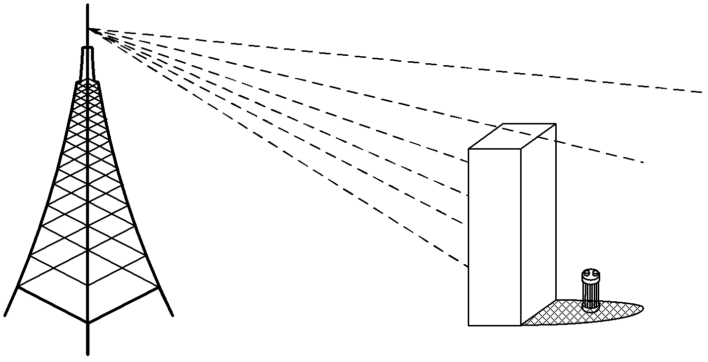
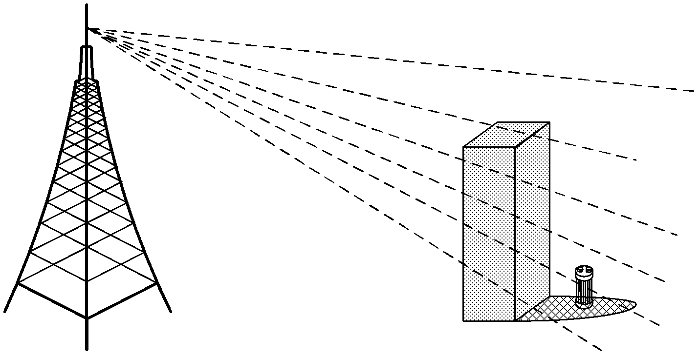
  • Method for improving covering range of field intensity of wireless communication network
  • Method for improving covering range of field intensity of wireless communication network
  • Method for improving covering range of field intensity of wireless communication network

Examples


Embodiment 1

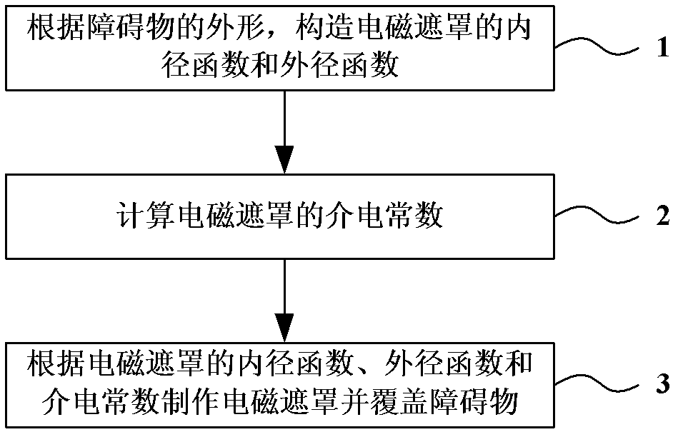
[0048] image 3 It is a flowchart of a method for improving the field strength coverage of a wireless communication network, image 3 Among them, the method for improving the field strength coverage of the wireless communication network in the present invention includes:

[0049] Step 1: Construct the inner radius function and outer radius function of the electromagnetic shield according to the shape of the obstacle.

[0050] In this embodiment, for the convenience of calculation, the electromagnetic shield is constructed as a sphere, and its inner radius function and outer radius function are respectively R 1 (θ) and R 2 (θ). Figure 4 is a schematic diagram of the inner and outer diameters of the spherical electromagnetic shield.

[0051] Step 2: Calculate the dielectric constant of the electromagnetic shield.

[0052] Since the electromagnetic shield in step 1 adopts a spherical shape, the inner radius function R of the electromagnetic shield 1 (θ) and outer diameter ...

Embodiment 2

[0073] According to formulas (9)-(13), it can be seen that when the first derivative of the inner diameter function of the electromagnetic shield and the outer diameter function of the electromagnetic shield are continuous, for example, when the electromagnetic shield adopts a spherical structure, the electromagnetic shield can be calculated anisotropic dielectric constant. When the first derivative of the inner diameter function of the electromagnetic shield or the outer diameter function of the electromagnetic shield is discontinuous, the dielectric constant of the electromagnetic shield can be calculated in the following manner.

[0074] Assuming that according to the shape of the obstacle, the electromagnetic shield constructed is rectangular, and its inner radius function and outer radius function based on polar coordinates are respectively:

[0075] R 1 ( θ ) = ...


PUM


Abstract

The invention, which belongs to the wireless communication technology field, discloses a method for improving a covering range of a field intensity of a wireless communication network. According to the method, an internal diameter function and an external diameter function of an electromagnetic shade are constructed according to a shape of an obstacle; when first order derivatives of the internal diameter function and the external diameter function are discontinuous, the internal diameter function and the external diameter function are fitted into a first and a second substitution functions by utilizing a fourier least-square-fitting method, wherein first order derivatives of the first and the second substitution functions are continuous; and a dielectric constant of the electromagnetic shade is calculated by utilizing the internal diameter function and the first substitution function as well as the external diameter function and the second substitution function; the electromagnetic shade is manufactured according to the internal diameter function, the external diameter function and the dielectric constant of the electromagnetic shade so as to cover the obstacle. According to the invention, a covering range of a wireless field intensity is effectively improved and shadow fading is eliminated.

Description

technical field [0001] The invention belongs to the technical field of wireless communication, and in particular relates to a method for improving the field intensity coverage of a wireless communication network. Background technique [0002] In the mobile wireless communication system, the electromagnetic wave emitted by the transmitter often has no direct path between it and the receiver due to the obstruction of the obstruction, so that the received signal strength decreases and the communication quality is difficult to control. Therefore, studying the method of increasing the field strength of the shaded area, that is, the shadow area and the weak field area, is beneficial to increase the field strength and coverage strength, extend the communication distance, and improve the communication quality. [0003] For the edge of the cell or the weak field area, it is usually compensated by adding a micro-cell structure, a relay node, or adjusting transmitter parameters. The c...

Claims


Application Information

Patent Timeline
Patent Type & Authority Applications(China)
IPC IPC(8): H04W16/26
Inventor 朱刚李元轩艾渤逯静辉许荣涛钟章队
Owner BEIJING JIAOTONG UNIV
Why Eureka
Try Eureka