
Ultra wide band antenna with reconfigurable frequency

An ultra-wideband antenna and frequency technology, which is applied in the field of ultra-wideband antennas, can solve the problems that the frequency sub-band cannot completely cover the ultra-wide band and the frequency sub-bands are not connected to each other, and achieves good pattern consistency, flat gain, and guaranteed radiation. The effect of efficiency

Inactive Publication Date: 2012-01-04
UNIV OF ELECTRONICS SCI & TECH OF CHINA
View PDF5 Cites 17 Cited by
  • Summary
  • Abstract
  • Description
  • Claims
  • Application Information

AI Technical Summary

Problems solved by technology

The disadvantage is that these multiple frequency sub-bands are not connected to each other, so the frequency sub-bands cannot completely cover the ultra-wide frequency band

Method used


Image

  • Ultra wide band antenna with reconfigurable frequency
  • Ultra wide band antenna with reconfigurable frequency
  • Ultra wide band antenna with reconfigurable frequency

Examples


Embodiment Construction

[0020] The present invention will be further described below in conjunction with the accompanying drawings and specific embodiments.

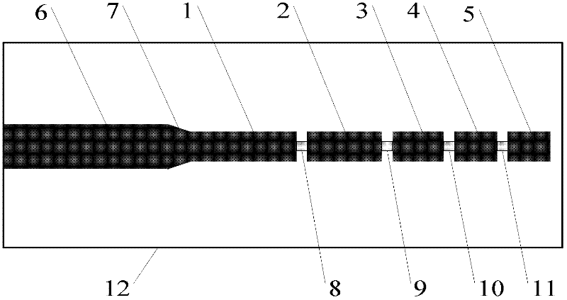
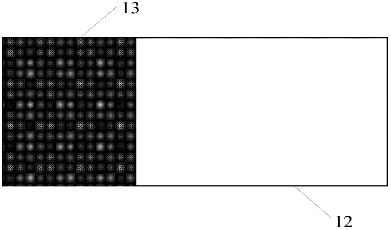
[0021] A frequency reconfigurable UWB antenna, such as Figure 1 to Figure 2 As shown, it includes: the first radiating unit 1, the second radiating unit 2, the third radiating unit 3, the fourth radiating unit 4, the fifth radiating unit 5, the microstrip feeder 6, and the transition microstrip 7 located on the front of the dielectric plate 12 , four electronic switches 8, 9, 10, 11 and a feeder grounding plate 13 located on the back of the dielectric board, and the dielectric board is located in the middle of the entire antenna. Here, the first radiating unit 1 , the second radiating unit 2 , the third radiating unit 3 , the fourth radiating unit 4 and the fifth radiating unit 5 constitute a printed monopole.

[0022] The radiation units 1, 2, 3, 4, and 5 are all rectangular metal patches with the same width and different lengths, and are ar...


PUM


Abstract

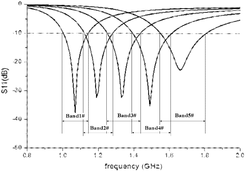
The invention belongs to the technical field of antennas and discloses an ultra wide band antenna with reconfigurable frequency. The antenna comprises a medium board, a micro band feeder, a transition micro band, a switch controller, a printed monopole which is positioned on the upper surface of the medium board, and a feeder grounding board which is positioned on the lower surface of the medium board, wherein the printed monopole comprises N radiating units which are arranged linearly; adjacent two radiating units are connected through an electronic switch; the switch controller is positioned on the lower surface of the feeder grounding board; and a control line of the switch controller is connected with (N-1) electronic switches for switching on or off the (N-1) electronic switches. The ultra wide band antenna provided by the invention overcomes the defects of the technologies of a traditional ultra wide band antenna and an antenna with reconfigurable frequency; the antenna can be switched for work in N continuous frequency sub bands and can cover an ultra wide band; simultaneously, the antenna also has the characteristics of flat gain, simple structure and the like in the ultra wide band; and the antenna can be applied for the fields of stepped-frequency ground penetrating radar systems and the like.

Description

technical field [0001] The invention belongs to the technical field of antennas, in particular to an ultra-wideband antenna. Background technique [0002] Stepped frequency ground penetrating radar (SFCW-GPR) is a continuous wave ground penetrating radar whose operating frequency is stepped in steps. In one scanning period, the frequency of the signal transmitted by the radar changes from the starting frequency f start Gradually rise to the stop frequency f with frequency interval Δf stop . For ground penetrating radar, ultra-wideband antenna is one of its key technologies. At present, the UWB antennas commonly used in ground penetrating radar systems mainly include: logarithmic periodic antennas, TEM horn antennas, junction antennas, cone antennas, and gradient slot antennas. These structural antennas can achieve an impedance bandwidth of several octaves, but there is a common defect. Due to the dispersion characteristics of the radiation performance, the electrical dim...

Claims


Application Information

Patent Timeline
IPC IPC(8): H01Q1/38H01Q9/30H01Q13/08
CPCH01Q13/206
Inventor 赵德双徐艳清兰立涛王秉中
Owner UNIV OF ELECTRONICS SCI & TECH OF CHINA
Learn More