Continuous coil and winding method thereof

A technology of coils and outer wires, which is applied in coil manufacturing, transformer/inductor coil/winding/connection, inductance/transformer/magnet manufacturing, etc., which can solve the difficulty of process operation, the selection of wire gauge height is too small, and the increase of manufacturing cost and other issues, to achieve the effect of improving coil space utilization, operating cost control, and reducing the number of oil passages

Inactive Publication Date: 2012-01-04
JIANGSU HUAPENG TRANSFORMER
View PDF5 Cites 2 Cited by
  • Summary
  • Abstract
  • Description
  • Claims
  • Application Information

AI Technical Summary

Problems solved by technology

On the low-voltage side of the ultra-high-voltage large-capacity transformer, such as the 110kV side, there are problems in selecting the coil type: if a spiral structure is used, the number of coil cakes is too large, and the space filling rate is poor, causing an increase in manufacturing costs; The height of the coil needs to correspond to the high-voltage coil, resulting in the selection of the height of the wire gauge being too small, which increases the difficulty of the process operation

Method used


Image

  • Continuous coil and winding method thereof
  • Continuous coil and winding method thereof
  • Continuous coil and winding method thereof

Examples


Embodiment 1

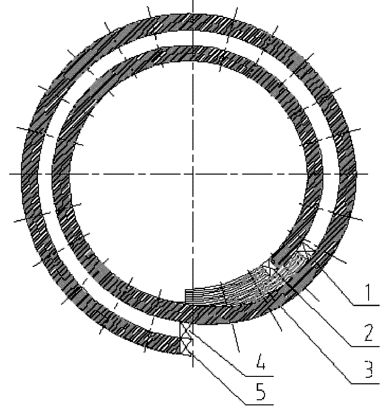
[0019] The continuous coil includes an inner wire and an outer wire wound outside the inner wire, the inner wire and the outer wire are intertwined to form at least two cakes; the outer wire in each cake is wound for one circle, and then transferred to the next cake; the outer wire After winding for two weeks, it is also transferred to the next cake. that is, figure 1 and figure 2 As shown, when winding, the winding starts from the first starting point 1 of the outer conductor and the second starting point 2 of the inner conductor. After one round of winding, the outer conductor B turns into the next one at the first end point 4, and the inner conductor A Then continue on the original line cake and make a circle again to its second end point 5 and then change to the next cake. The number of turns per pie is 2A+B or A+2B, A and B are parallel wires, if the total current per turn (2 parallel windings) is I, then the current flowing through each pie is 2×(0.5I) +0.5I or 0.5I+...

Embodiment 2

[0022] The winding method of the continuous coil of the present invention comprises the following steps: firstly, the inner wire in each cake is wound for one week and then transferred to the next cake; secondly, after the inner wire in each cake is wound for two weeks, it is also transferred to the next cake a cake. that is, figure 1 and figure 2 As shown, firstly, when winding, the winding starts from the first starting point 1 of the outer conductor and the second starting point 2 of the inner conductor, and after one round of winding, the outer conductor B turns into the next 1 cake at its first end point 4; secondly , the inner conductor A then continues to wind another circle on the original line cake to its second end point 5 and then transfers to the next cake. The number of turns per pie is 2A+B or A+2B, A and B are parallel wires, if the total current per turn (2 parallel windings) is I, then the current flowing through each pie is 2×(0.5I) +0.5I or 0.5I+2×(0.5I)...


PUM


Abstract

The invention discloses a continuous coil which comprises an inner conductor and an outer conductor which is wound on the outer side of the inner conductor, wherein the inner conductor and the outer conductor are mutually wound to form at least two cakes; the outer conductor in each cake is wound for a circle, and then transferred to the next cake; and the outer conductor is wound for two circles, and then transferred to the next cake. The invention also discloses a winding method of the continuous coil, which comprises the following steps: firstly, winding the inner conductor in each cake for a circle and subsequently transferring to the next cake; and then, winding the inner conductor in each cake for two circles and transferring to the next cake. Therefore, the number of coil cakes is greatly reduced so that the number of oil channels among the cakes is reduced and the utilization rate of coil space is enhanced; simultaneously, over small number of the cakes with two circles of each cake is avoided so that larger vortex loss caused by overlarge size of conductor height is avoided; load loss during operation of a transformer is reduced; and operating cost is controlled.

Description

technical field [0001] The invention relates to a continuous coil and a winding method of the continuous coil. [0002] Background technique [0003] In a power system, a transformer is a key device for transmitting electrical energy. During the transmission of electric energy from the power plant to the user end, multi-stage step-up, step-down and contact transformers are required. According to different voltage levels and capacities, different types of coil structures are used in the design and manufacture of transformers. Among them, the continuous coil is the most widely used coil structure type. [0004] The number of mechanical turns of the traditional continuous coil can be wound in fractional turns. The coils in each cake are in the same plane, and the coils are wound close to each other. The number of electrical turns of the coil can only be an integer. On the low-voltage side of the ultra-high-voltage large-capacity transformer, such as the 110kV side, there ar...

Claims


Application Information

Patent Timeline
Patent Type & Authority Applications(China)
IPC IPC(8): H01F27/28H01F41/06H01F41/074
Inventor 陈琪张月江帆
Owner JIANGSU HUAPENG TRANSFORMER
Why Eureka
Try Eureka