Combined comb

A combined, comb technology, applied in hair combs, clothing, hairdressing equipment, etc., can solve the problems of dull appearance, inability to remove or replace, and heavy production, and achieve the effect of simple coordination and convenient use.

Active Publication Date: 2013-09-18
JIANGSU UNIV OF TECH
View PDF8 Cites 0 Cited by
  • Summary
  • Abstract
  • Description
  • Claims
  • Application Information

AI Technical Summary

Problems solved by technology

Because the wooden comb made of the whole piece of miscellaneous wood is easy to deform, especially the comb teeth are easy to break or deform, so it is made thick and looks dull
In addition, if a comb tooth is broken or deformed, since it cannot be removed or replaced, it can only be scrapped or used as a makeshift
[0006] Chinese patent document CN 2715597Y (application number 200420059565.9, hereinafter referred to as reference document 1) discloses a mosaic structure multifunctional comb. The comb in this document includes a comb beam and comb teeth, and a concave groove is opened on the lower part of the comb beam. , a structure of which is provided by claims 1 and 2: the comb teeth are composed of several single-body comb teeth, and convex joints are respectively arranged on the upper parts of the comb teeth, and the comb teeth are pressed and arranged on the comb teeth through the joint parts. In the groove position of the lower part of the comb beam, and make the joint part be completely hidden in the groove position, the technical feature of making the comb tooth roots flush with the bottom edge of the comb beam is given in the utility model content part; in embodiment 1, Describes the shape of the junction of its comb teeth as trapezoidal, while its image 3 The hypotenuses of the trapezoid shown in the figure are set on the left and right sides, from which the following conclusions can be drawn: if the individual comb racks are placed in the slots in this embodiment by pressing, the adjacent racks will be pressed The inconsistency of fastness will cause the loosely pressed rack to fall off during use
This document also does not solve the problem that if the comb teeth are broken or deformed, they can still only be scrapped or used

Method used


Image

  • Combined comb
  • Combined comb
  • Combined comb

Examples


Embodiment 1

[0058] (Embodiment 1, combined comb)

[0059] See figure 1 and figure 2 , the combined comb of the present embodiment (combined comb and combined comb) is a combined comb. The combined comb includes a horizontally arranged handle 1 and a horizontally arranged comb member 2a as a tooth member 2, and the tooth member 2 includes a horizontally arranged root plate 21 and an overall horizontally arranged comb connected to the root plate 21 A set of comb teeth 22 , and the tooth tips of the comb teeth 22 are located in front of the root plate 21 . The combined comb is composed of a comb member 2a and a handle 1 inserted in the left and right directions and detachably fitted with interference.

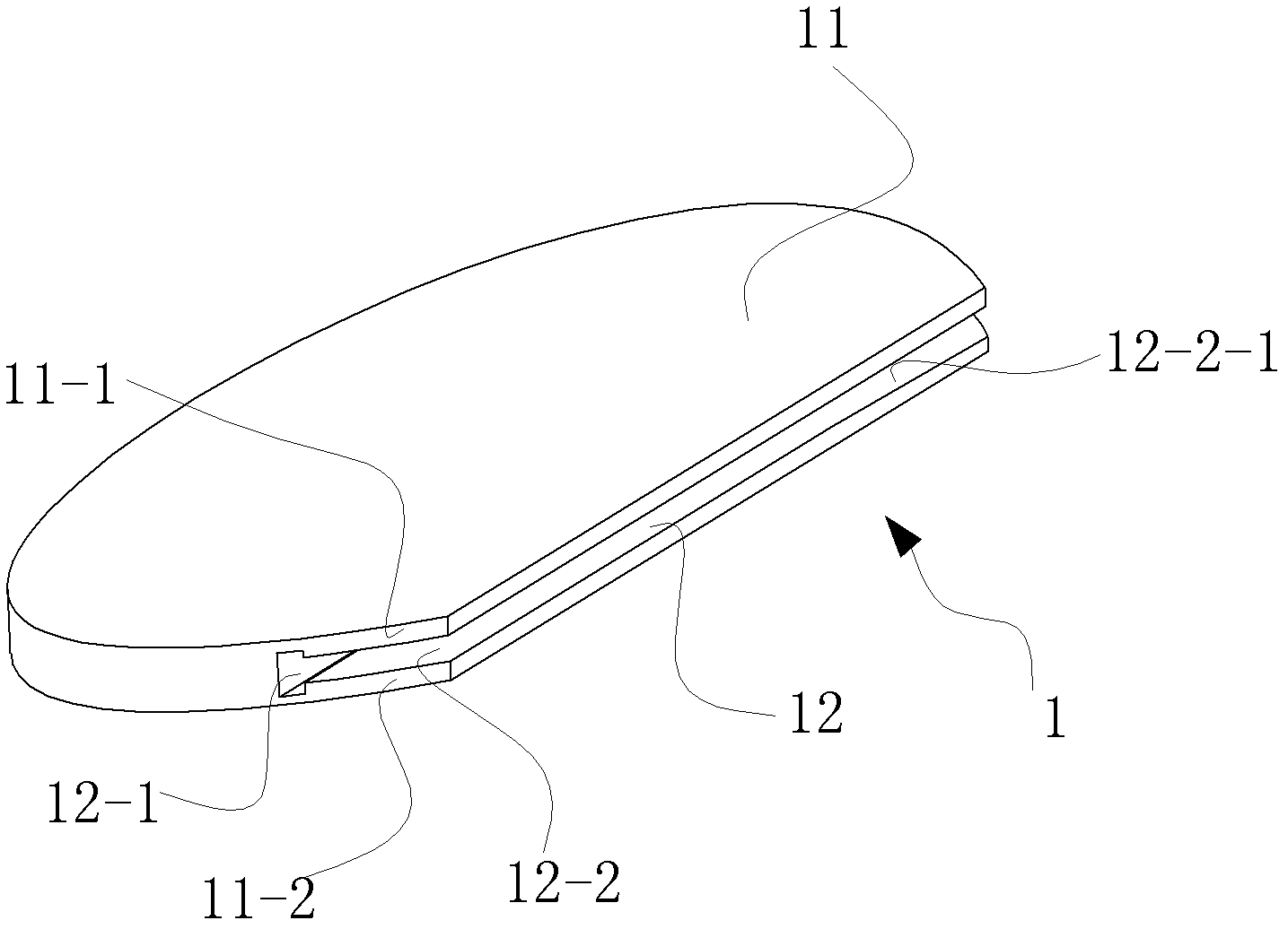
[0060] See figure 1 The handle 1 includes a handle body 11 and an insertion slot 12 disposed on the handle body 11 along the left and right directions and located at the front of the handle body 11 , the insertion slot 12 is provided with a front notch facing forward.

[0061] still s...

Embodiment 2

[0071] (Example 2, combined grate)

[0072] See figure 1 , image 3 and Figure 4 , The combined comb grate of the present embodiment is a combined comb grate. The combined grate includes a horizontally arranged handle 1 and a horizontally arranged grate member 2b as a tooth member 2. The combined grate is formed by inserting the grate member 2b and the handle 1 along the left and right directions and detachable interference fit. The handle 1 of this embodiment is the same as that of Embodiment 1.

[0073] See image 3 , The grate tooth member 2b is composed of a grate tooth root plate 21b, a set of grate tooth 22b and two retaining bars 23; the grate tooth root plate 21b is made up of an upper splint 21b-1 and a lower splint 21b-2. And composed of split panels. The grate teeth of the above-mentioned group of grate teeth 22b are arranged in a row to form a grate tooth group, and then a retaining bar 23 is respectively arranged on the left and right sides of the grate toot...

Embodiment 3

[0080] (Embodiment 3, combined comb)

[0081] The remainder of the combined grate of the present embodiment is identical with embodiment 1, and difference is:

[0082] See Figure 5 The insertion groove 12 of the handle 1 is a groove with left and right groove walls arranged on the handle main body 11, that is, the left and right ends of the insertion groove 12 of the handle 1 are in a closed state, and the insertion direction of the insertion groove 12 For forward and backward. The cross-section of the insertion slot 12 is a trapezoid placed transversely. The insertion groove 12 is located at the left-right central part of the front portion of the handle main body 11; The distance between the groove wall and the right end of the front end surface of the handle main body 11 is 5 mm to 25 mm. The distance between the upper groove wall and the lower groove wall of the insertion groove 12 gradually decreases from front to back, so that the insertion groove 12 is an inclined p...


PUM


Abstract

The invention discloses a combined comb, which comprises a handle and a tooth component; the handle comprises a handle main body and a splicing groove, wherein the splicing groove is formed in the handle main body, and forward-opened; the tooth component is a comb tooth component or a fine tooth component; and the tooth component comprises a root board piece and a group of comb teeth connected to the root board piece, the root board piece of the tooth component is mutually spliced with the splicing groove of the handle, the root board piece of the tooth component is in interference fit with the splicing groove of the handle, and the upper and lower lateral surfaces of the root board piece of the tooth component are in contact with the corresponding walls of an installation groove. The handle is matched with the comb tooth part simply and effectively; and when the comb teeth are damaged, the tooth component can be timely changed, so that the service life of the comb is prolonged.

Description

technical field [0001] The invention relates to a comb, in particular to a combined comb. Background technique [0002] Comb is a general term for comb and grate. The traditional grate is a combing utensil made of materials such as bamboo and ox bone. There is a grate beam in the middle, and one side of the two sides is provided with fine teeth and the other side is provided with sparse teeth. The grate has both practical and symbolic functions. On the one hand, the teeth on the denser side of the grate are denser, so it can be used to scrape dandruff and lice hidden in the hair; Gently comb the head to massage the scalp and relax the tendons. [0003] The manufacturing process of the traditional grate is meticulous and complicated, and there are many processes, requiring 108 "hands and feet". The process is mainly divided into the following steps: ① making blanks, selecting suitable bamboo, opening the green grate bamboo slices with a grate knife, peeling off the green s...

Claims


Application Information

Patent Timeline
Patent Type & Authority Patents(China)
IPC IPC(8): A45D24/00A45D24/02
Inventor 郭琳
Owner JIANGSU UNIV OF TECH
Why Eureka
Try Eureka