Composite spinning device and spinning method for chemical fiber filament coated rigid fiber filament
A rigid fiber and composite spinning technology, which is applied in the direction of continuous winding spinning machine, spinning machine, yarn, etc., can solve the problems of fiber bending and brittleness, general effect, etc., and achieve good tension, quality assurance, and controllability strong effect
- Summary
- Abstract
- Description
- Claims
- Application Information
AI Technical Summary
Problems solved by technology
Method used
Image
Examples
Embodiment 1
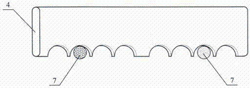
[0028] Such as figure 1 As shown, it is a composite spinning device in which chemical fiber filaments are coated with rigid fiber filaments, figure 2 As a side view, the composite spinning device is provided with an unwinding roller 1, a positioning guide 2, a tension disc 3, a multi-position yarn guide 4 and a fixed frame 5 on the ring spinning frame, and the positioning guide The device 2 is located behind the feeding nip of the front roller pair 11 of the ring spinning frame, the multi-position yarn guide 4 is located in front of the output nip of the front roller pair 11 of the ring spinning frame, the unwinding roller 1, the tension disc 3 and the multi-position yarn guide 4 are arranged on the fixed frame 5, and the unwinding roller 1 is composed of a pair of rubber rollers that are pressed against each other, and it can move on the fixed frame 5. There are two tension discs 3 arranged symmetrically. The multi-position yarn guide 4 has a plurality of symmetrically arr...
Embodiment 2
[0030] Using the composite spinning device described in Example 1, the carbon fiber filament is used as the rigid fiber filament 6, and the polyester filament is used as the chemical fiber filament 7, and the rigid fiber filament 6 that is unwound from the rigid fiber filament tube After successively passing through the unwinding roller 1 and the positioning guide 2, it is fed into the front roller pair 11 through the tension disc 3 and the multi-position yarn guide 4, and then output symmetrically from the front roller pair 11. The two bundles of chemical fiber filaments 7 converge at the converging point 10, and at the same time, under the rotation of the spindle 9 of the ring spinning frame, the chemical fiber filaments 7 and rigid fiber filaments 6 are turned and twisted at the converging point 10 to form chemical fiber filaments 7 Composite yarn 8 wrapped on the outside of rigid fiber filament 6. Such as Figure 4 Shown is a schematic diagram of the composite yarn struct...
Embodiment 3
[0032] Using the composite spinning device described in Example 1, the glass filament is used as the rigid fiber filament 6, and the polypropylene filament is used as the chemical fiber filament 7, and the rigid fiber filament 6 that is unwound from the rigid fiber filament tube After successively passing through the unwinding roller 1 and the positioning guide 2, it is fed into the front roller pair 11 through the tension disc 3 and the multi-position yarn guide 4, and then output symmetrically from the front roller pair 11. The two bundles of chemical fiber filaments 7 converge at the converging point 10, and at the same time, under the rotation of the spindle 9 of the ring spinning frame, the chemical fiber filaments 7 and rigid fiber filaments 6 are turned and twisted at the converging point 10 to form chemical fiber filaments 7 Composite yarn 8 wrapped on the outside of rigid fiber filament 6. Such as Figure 4 Shown is a schematic diagram of the composite yarn structure...
PUM
 Abstract
Description
Claims
Application Information
 - R&D
- Intellectual Property
- Life Sciences
- Materials
- Tech Scout
- Unparalleled Data Quality
- Higher Quality Content
- 60% Fewer Hallucinations
Browse by: Latest US Patents, China's latest patents, Technical Efficacy Thesaurus, Application Domain, Technology Topic, Popular Technical Reports.
© 2025 PatSnap. All rights reserved.Legal|Privacy policy|Modern Slavery Act Transparency Statement|Sitemap|About US| Contact US: help@patsnap.com


