


Quick Research
Generate reliable direction feasibility study reports for your R&D in just a few steps.

Technical Q&A
Discover and master advanced knowledge NOW. Basics, ideas, possibilities, all at once.

Find Solutions
As an expert in R&D theories, this can generate solutions to your technical problems instantly.

Evaluate Feasibility
Analyze your overall solution with one click, know your potential R&D risks in advance.

Monitor Landscape
Get weekly tech updates, stay abreast of the latest tech innovations and key insights.
Heat treatment quenching cooling device
A cooling device and cooling pool technology, applied in quenching devices, heat treatment equipment, manufacturing tools, etc., can solve the problems of unsatisfactory cooling effect, prone to safety accidents, unsatisfactory cooling effect, etc., to achieve ideal heat dissipation effect and not easy to safety accidents. , Conducive to the effect of heat dissipation
- Summary
- Abstract
- Description
- Claims
- Application Information
AI Technical Summary
Problems solved by technology
Method used
Image

Examples
Embodiment Construction
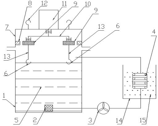
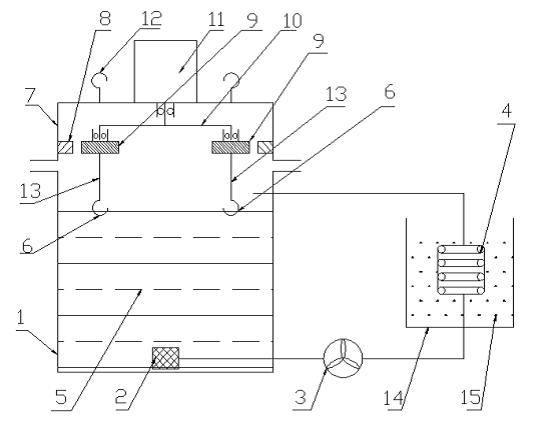
[0011] In the figure, the heat treatment quenching cooling device includes a cooling pool 1, an oil filter 2, an oil pump 3, a radiator 4, cooling oil 5, a hook 6, a box body 7, a large internal gear 8, a planetary gear 9, and a planetary gear carrier 10. The cooling system of motor 11, lifting frame 12, suspension shaft 13, cooling tank 14, circulating water 15, the present invention is provided with a cooling pool 1, oil filter 2, oil pump, 3 radiator 4, cooling oil 5, Cooling tank 14, the cooling system of circulating water 15, the cooling pool 1 of this invention is independent of each other, the oil inlet of oil pump 3 communicates with the bottom of cooling pool 1 through oil filter 2; The upper mouth of the cooling pool is connected, and cooling oil 5 is injected in the cooling pool. The cooling tank 14 is independent of the cooling pool 1. The radiator 4 is fixedly installed in the cooling tank 14, and the circulating water 15 is introduced in the cooling tank. At the ...
PUM
 Abstract
Description
Claims
Application Information
 - R&D Engineer
- R&D Manager
- IP Professional
- Industry Leading Data Capabilities
- Powerful AI technology
- Patent DNA Extraction
Browse by: Latest US Patents, China's latest patents, Technical Efficacy Thesaurus, Application Domain, Technology Topic, Popular Technical Reports.
© 2024 PatSnap. All rights reserved.Legal|Privacy policy|Modern Slavery Act Transparency Statement|Sitemap|About US| Contact US: help@patsnap.com