
Tooling for machining steam turbine condenser air extraction pipe

A technology for condensers and steam turbines, applied to metal processing machinery parts, metal processing equipment, manufacturing tools, etc., can solve the problems of low drilling success rate, high scrap rate, scrapped processed tubes, etc., and achieve drilling success efficiency High, high position accuracy, not easy to scrap effect

Active Publication Date: 2011-12-28
HARBIN TURBINE +1
View PDF6 Cites 3 Cited by
  • Summary
  • Abstract
  • Description
  • Claims
  • Application Information

AI Technical Summary

Problems solved by technology

[0003] The purpose of the present invention is to solve the problem of using two V-shaped irons to support the processed pipe for the processing of the existing steam turbine condenser air extraction pipe, and directly drill the air extraction hole on the rocker drill, so that the drilling position is inaccurate and the position accuracy is poor. The processed tubes are scrapped, the drilling success rate is low, and the scrap rate is high. A tool for processing steam turbine condenser air extraction tubes is provided.

Method used


Image

  • Tooling for machining steam turbine condenser air extraction pipe
  • Tooling for machining steam turbine condenser air extraction pipe
  • Tooling for machining steam turbine condenser air extraction pipe

Examples


specific Embodiment approach 1

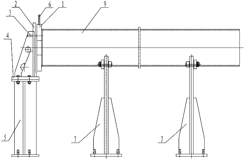
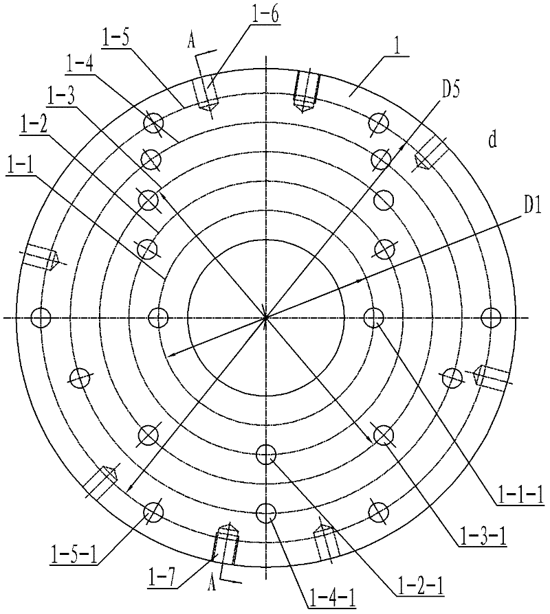
[0007] Specific implementation mode one: combine Figure 1 to Figure 8 Describe this embodiment, this embodiment comprises indexing plate 1, positioning plate 2, positioning pin 3, seat plate 4, supporting base 5, at least one rotating rod 6 and two support frames 7, on described indexing plate 1 is made up of There are five pitch circles with increasing diameters concentrically from the inside to the outside. The five pitch circles are the first pitch circle 1-1, the second pitch circle 1-2, and the third pitch circle. 1-3, the fourth pitch circle 1-4 and the fifth pitch circle 1-5, the distance between each adjacent two pitch circles is equal, and the first pitch circle 1-1 is laid There are at least two first indexing holes 1-1-1, several second indexing holes 1-2-1 are evenly arranged on the second indexing pitch circle 1-2, and several second indexing holes 1-2-1 are arranged on the third indexing pitch circle 1-3. Several third indexing holes 1-3-1 are evenly distribute...

specific Embodiment approach 2

[0009] Specific implementation mode two: combination figure 2 and image 3 To describe the present embodiment, at least one threaded hole 1-7 is provided on the circumferential surface of the index plate 1 of the present embodiment. The threaded holes 1-7 are used to install suspension rings, which is convenient for lifting the indexing plate 1. Other components and connections are the same as those in the first embodiment.

specific Embodiment approach 3

[0010] Specific implementation mode three: combination image 3 This embodiment is described. The difference between this embodiment and the first embodiment is that it also adds ribs 8 . Rib 8 plays the role of supporting positioning plate 2 . Other components and connections are the same as those in the first embodiment.


PUM


Abstract

The invention discloses a tool for processing an air extracting pipe of a condenser of a turbine, which relates to an auxiliary tool for processing the air extracting pipe of the condenser of the turbine and aims to solve the problems that a processed pipe is supported by two pieces of V-shaped iron, air extracting holes are directly drilled on a radial drill, the positions of the drilled holes are inaccurate and the drilled holes have low precision in the conventional tool for processing the air extracting pipe of the condenser of the turbine. A rotating rod is arranged in an installation hole; a positioning plate and an indexing disk are arranged in parallel; the center line of the positioning plate is opposite to the center line of the indexing disk; two long holes are formed between afirst positioning pitch circle and a second positioning pitch circle on the positioning plate; the width of each long hole is equal to the diameter of an indexing hole; an included angle between the two long holes is 90 degrees; positioning pins are arranged in the long holes and the indexing holes; the lower end of the positioning plate is connected with a bearing seat by a seat plate; the indexing disk, the positioning plate, the components of the bearing seat and two support frames are sequentially arranged along a longitudinal direction; and the vertical center lines of frame bodies and the center line of the indexing disk are positioned in the same plane. The tool is used for processing the air extracting pipe of the condenser of the turbine.

Description

technical field [0001] The invention relates to an auxiliary tool for processing steam turbine condenser air extraction pipes. Background technique [0002] Use the exhaust pipe of the steam turbine condenser to extract the residual gas inside the condenser shell to ensure the negative pressure of the condenser shell, so that the condenser can work normally. Several air extraction holes are processed on the top; the processing method of the existing steam turbine condenser air extraction pipe is: use two V-shaped irons to support the processed pipe, and directly drill the air extraction holes on the rocker drill. This method makes the drilling position inaccurate , The position accuracy is poor, it is easy to cause the processed tube to be scrapped, the drilling success rate is low, and the scrap rate is high. Contents of the invention [0003] The purpose of the present invention is to solve the problem of using two V-shaped irons to support the processed pipe for the pr...

Claims


Application Information

Patent Timeline
IPC IPC(8): B23B41/02B23Q16/02
Inventor 卢波姚青文张俊成太秀滨李文涛张仁军
Owner HARBIN TURBINE
Learn More