
A low-cost and high-precision resistance measurement system and its measurement method

A resistance measurement, high-precision technology, applied in the field of measurement, can solve problems such as inability to completely eliminate errors and high price

Inactive Publication Date: 2011-12-21
钟小梅
View PDF4 Cites 29 Cited by
  • Summary
  • Abstract
  • Description
  • Claims
  • Application Information

AI Technical Summary

Problems solved by technology

[0006] The purpose of the present invention is to aim at the instrument in the process of measuring the physical quantity, in order to improve the measurement accuracy of the resistance, it is necessary to use an expensive, high-precision, low-temperature drift current source and voltage measurement circuit, and even so the problem that the error cannot be completely eliminated , a low-cost high-precision resistance measurement system and its measurement method are proposed; specifically, the on-line calibration method is used to calibrate the measurement resistance according to the standard resistance at the input end, which completely eliminates the problems introduced by the current source and voltage measurement circuit in theory. Error, in order to achieve the purpose of high-precision measurement with low-cost circuits

Method used


Image

  • A low-cost and high-precision resistance measurement system and its measurement method
  • A low-cost and high-precision resistance measurement system and its measurement method
  • A low-cost and high-precision resistance measurement system and its measurement method

Examples


Embodiment Construction

[0036] The present invention will be further described below in conjunction with the accompanying drawings and embodiments.

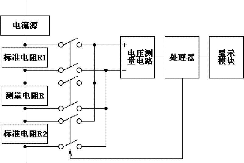
[0037] A low-cost and high-precision resistance measurement system, which includes a current source, a multi-channel linkage switch, a voltage measurement circuit, a processor, and a display module, which can be connected in the following two ways:

[0038] (a) if figure 1 As shown, the measuring resistor R and at least one standard resistor are connected in series to the current source, the two ends of the measuring resistor R and each standard resistor are respectively connected to the input terminals of each linkage switch, and the output terminals of all linkage switches are connected in parallel to the positive voltage measurement circuit. , Negative input terminal, the signal output terminal of the voltage measurement circuit is connected to the processor, the control signal output terminal of the processor is connected to the linkage switch switc...


PUM


Abstract

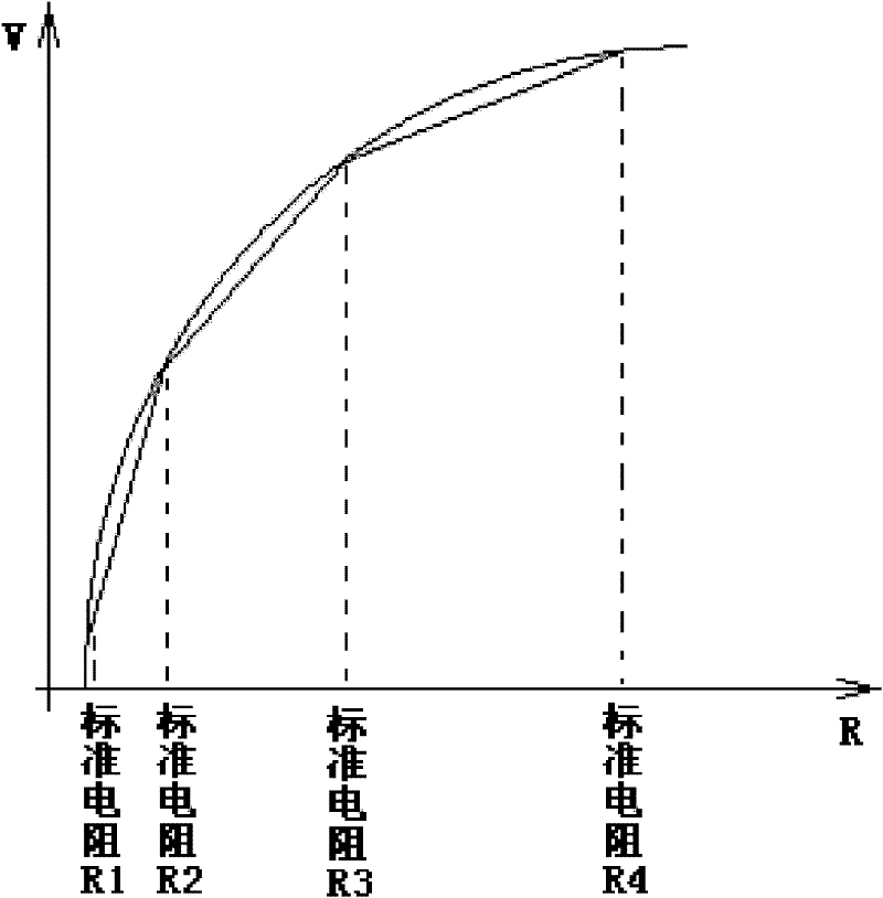
A low-cost and high-precision resistance measurement system and its measurement method, including a current source, a multi-channel linkage switch, a voltage measurement circuit, a processor, and a display module. The processor switches the input resistance through the multi-channel linkage switch to a standard resistance R1 in sequence , R2, read the output of the voltage measurement circuit, and substitute into the transmission equation to solve, then switch the input to measure the resistance, obtain the value of the measurement resistance according to the transmission equation and the voltage measurement circuit output voltage; in the present invention, only the linearity of the voltage measurement circuit The error is small enough, and the error of the measured resistance is only related to the standard resistance, which theoretically eliminates the errors caused by the current source and voltage measurement circuits, such as differential processing circuits, A / D converters, etc. The low-cost current source and voltage measurement circuit can realize the purpose of measuring resistance with high precision; the standard resistance in the present invention must be used in the precision current source of conventional resistance measurement circuit, and no need to increase the cost.

Description

technical field [0001] The present invention relates to a measurement method, especially a system and method for calibrating and measuring resistance according to the standard resistance of the input terminal by using an online calibration method, specifically a low-cost and high-precision resistance measurement method and a device using the method measuring system. [0002] Background technique [0003] At present, many sensors (such as thermistors) used to measure physical quantities convert the signal to be measured into a resistance signal, and then obtain the actual value of the measured physical quantity by measuring the resistance signal; therefore, the accuracy of the measurement of the resistance signal The accuracy directly determines the accuracy of the measured physical value. [0004] The traditional measurement method is to add a known current to the resistance signal output by the sensor, then measure the voltage value at both ends, calculate the resistance ...

Claims


Application Information

Patent Timeline
IPC IPC(8): G01R27/14
Inventor 钟小梅
Owner 钟小梅
Learn More