
Liquid level variable and gear variable combination high-precision measurement method and device

A technology for measuring and measuring and measuring devices, which is applied to measuring devices, liquid/fluid solids measurement, and optical devices, etc., and can solve the problems of large cumulative error, unmatched products, and inability to collect accurately.

Inactive Publication Date: 2011-12-21
周泉清
View PDF5 Cites 2 Cited by
  • Summary
  • Abstract
  • Description
  • Claims
  • Application Information

AI Technical Summary

Problems solved by technology

[0002] In industrial and agricultural production, national defense construction, and scientific research, it is necessary to accurately measure the length and displacement of objects, such as servo motors, displacement sensors, and vernier calipers commonly used in mechanical industry production. These measuring instruments and measuring tools are often Due to the inability to accurately locate the initial zero point and the inability to accurately locate the measurement end point, a large error occurs in microscopic measurement; there are different gaps and different errors in the movement of mechanical components such as motors, gears, bearings, and bearing bushes. Therefore, the servo motor It is difficult to accurately accept the ideal displacement data command and control of NC programming; the precision of machinery and bearing bushes is low, the gap is large, the radial and lateral runout is large, and the cumulative error is large, which seriously restricts the accurate collection of data signals by photoelectric sensors and other measuring instruments. It restricts the accuracy of measurement and displacement to the micron and nanometer level; due to the gap error in the mechanical transmission part itself, even the advanced precision machine tool is about 20-50 microns, so the precision machine tool cannot make the processed parts reach the micron level Even higher-level nanoscale; even if the machine tool is more precise, the gap will gradually increase after long-term wear and tear. According to the established programming, there will be errors of varying degrees. The error of the parts processed by the new machine tool is also less standard, and the machine tool produced by the same process often has the phenomenon that the products produced are not matched; the laser infrared rangefinder can measure accurately, but due to the error of the mechanical transmission, it cannot Accurately determine the zero point of the initial count, the accurate signal cannot be collected, and the end point of the end count cannot be accurately determined, and the collected data is also error data; similarly, when moving back and forth, there will be multiple zero points of the initial count. The gap error of the transmission parts, every time the zero point of the initial count is collected, there will be multiple errors, coupled with multiple reciprocating transmissions, it will also lead to multiple accumulated gap errors, and the processed parts cannot meet the design requirements
Therefore, traditional measurement technology and measurement devices cannot meet the needs of rapidly developing industrial and agricultural production, national defense construction and scientific research, restricting the development and application of science and technology, and becoming a technical problem in the field of physical measurement and measurement

Method used


Image

  • Liquid level variable and gear variable combination high-precision measurement method and device
  • Liquid level variable and gear variable combination high-precision measurement method and device

Examples


Embodiment Construction

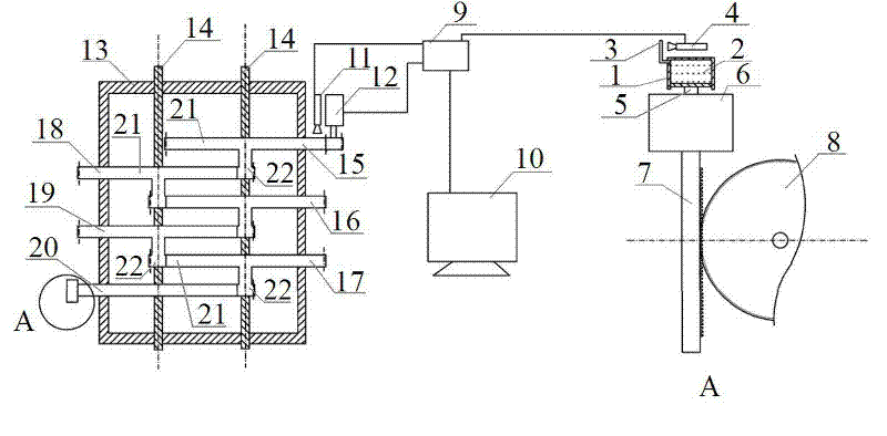
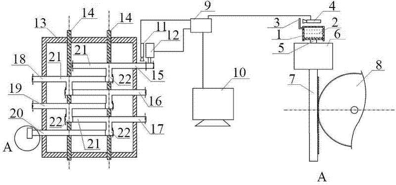
[0060] Referring to the accompanying drawings, the liquid level variable and gear variable combination high-precision measurement method of the present invention is:

[0061] 1) Place the measured object between the hydraulic container or oil cylinder liquid level variable precision measuring device and the gear variable combiner, make sure that the hydraulic container or oil cylinder liquid level variable precise measurement measuring device is closely matched with the measured object without gap, and When the gear variable combiner is pushed by external force, determine the true zero position or displacement under the conditions of eliminating the gap, overcoming the mass of the object, and frictional resistance; or accurately measure the liquid level variable of the hydraulic container or cylinder with the output of the servo motor output or the push device The ends are closely matched to determine the real zero point or displacement of the output end after overcoming the re...


PUM


Abstract

The invention discloses a liquid-level variable and gear variable combined high-precision measuring and metering method and a device. The device comprises three parts of a hydraulic container or cylinder liquid-level variable precise measuring and metering device, a gear variable combiner and an electronic information control device. The bottom of the large-aperture hydraulic container or cylinder provided with a piston is communicated with a small-aperture measurement pipe. The gear variable combiner is as follows: a plurality of meshed large gears and small gears are installed in a gearbox;and the gear perimeter transmission ratio is the magnifying power and the reducing power of the gear variable count. The electronic information control device comprises a computer, a controller, an infrared electronic measurement ruler and a stepping motor which are mutually and electrically connected. An output gear rack or a measurement head of the gear variable combiner and a piston connectingrod of the hydraulic container or cylinder are tightly matched with an object to be measured so that the object to be measured is located and measured accurately. The device disclosed by the invention has the advantages of high measuring and metering precision and accurate zero point location and can be widely applicable in the fields, such as numerical control machines, sighting devices, preciseinstruments, balanced pressures, standard length weights and the like. A novel measuring and metering instrument and a tool for agricultural and industrial production, national defence construction and scientific research are provided.

Description

technical field [0001] The invention relates to the technical field of measurement and measurement, in particular to a method and device for high-precision measurement and measurement of a liquid level variable and a gear variable combination using a combination of a liquid level variable of a hydraulic container or an oil cylinder and a gear variable driven by multiple sets of gears. Background technique [0002] In industrial and agricultural production, national defense construction, and scientific research, it is necessary to accurately measure the length and displacement of objects, such as servo motors, displacement sensors, and vernier calipers commonly used in mechanical industry production. These measuring instruments and measuring tools are often Due to the inability to accurately locate the initial zero point and the inability to accurately locate the measurement end point, a large error occurs in microscopic measurement; there are different gaps and different erro...

Claims


Application Information

Patent Timeline
IPC IPC(8): G01B11/02G01F23/292
Inventor 周泉清
Owner 周泉清
Learn More