
Chip mounter

A placement machine, patch technology, applied in the direction of electrical components, electrical components, electrical components to assemble printed circuits, etc., can solve the problems of time-consuming and laborious, waste of work area, low work efficiency, etc., to achieve convenient installation and use, improve transmission The effect of speed and high work efficiency

Inactive Publication Date: 2014-05-14
JIANGXI WANSHEN MACHINERY
View PDF3 Cites 0 Cited by
  • Summary
  • Abstract
  • Description
  • Claims
  • Application Information

AI Technical Summary

Problems solved by technology

For example, the relatively mature and widely used placement machine has only one set of conveyor belts, and the circuit board is supported by two narrow belts at the front and rear, and the middle is empty. Although this structure is simple, it can only wait for one line when working. After the board is out of the board, the next circuit board can enter the board, which wastes a lot of time, and the phenomenon of sinking in the middle of the circuit board may occur, which affects the placement effect; low work efficiency and poor reliability
[0003] In addition, the existing placement machine nozzle replacement device is fixed on one side of the machine and is within the working area of ​​the placement machine, so collisions may occur during the placement programming process; the usual solution is In the software, set this area as a special area for nozzle replacement, not as a working area, but doing so will waste a large area of ​​working area and increase the size of the placement machine
[0004] There is also a feeding device. The feeding devices used in the existing placement machines are all one-to-one, that is to say, each material needs to be installed in a feeding device, and a feeding device corresponds to a driver; This kind of feeding device has a complex structure and relatively high price. Generally speaking, the feeding device accounts for about 30% of the total price of a placement machine;
[0005] And a placement machine often needs to adapt to many different specifications and types of circuit board placement, and the components to be mounted on each circuit board are different. At this time, it is necessary to install the installed feeding device one by one. Replacing it is time-consuming and labor-intensive, and it is particularly troublesome

Method used

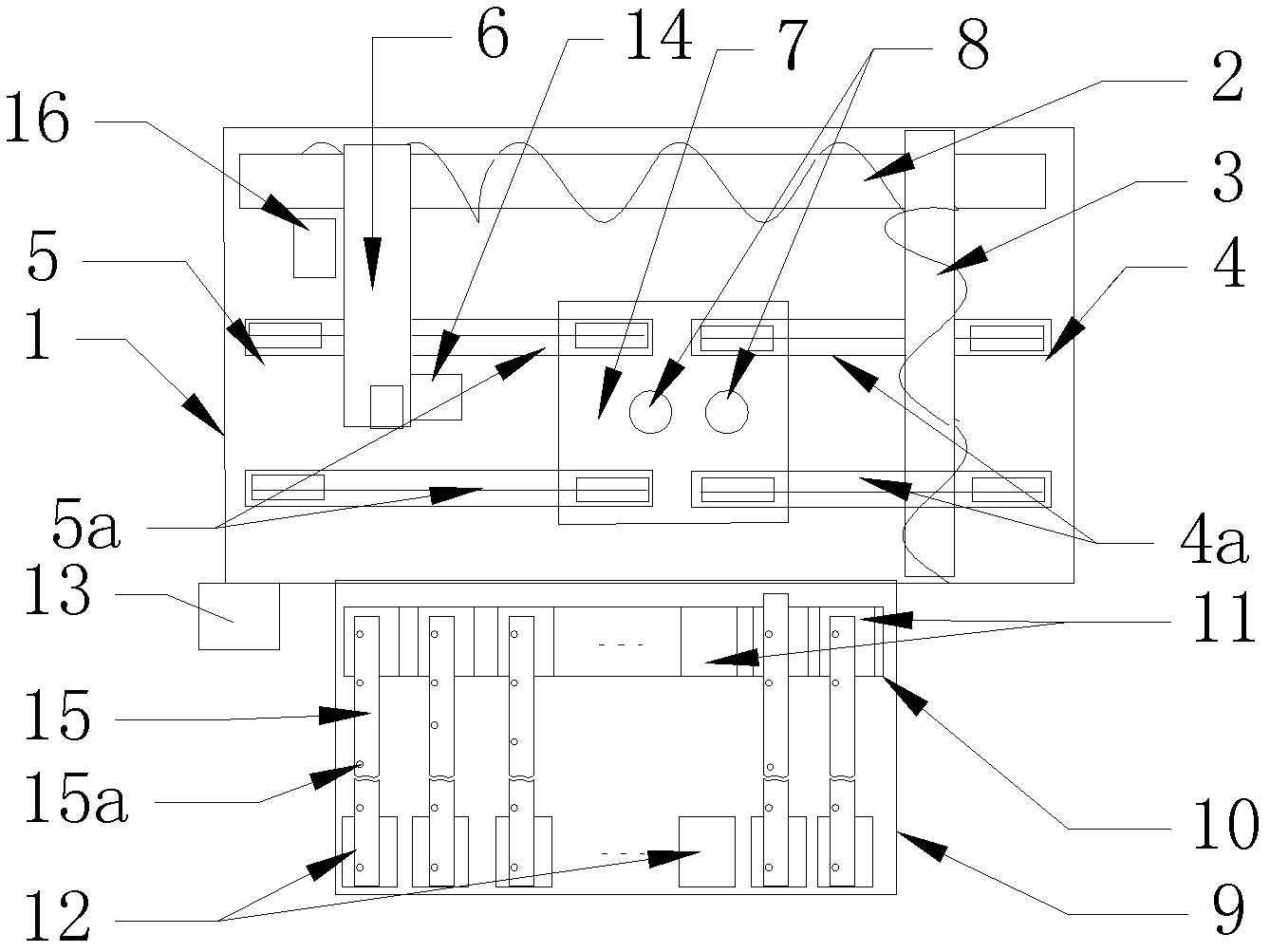
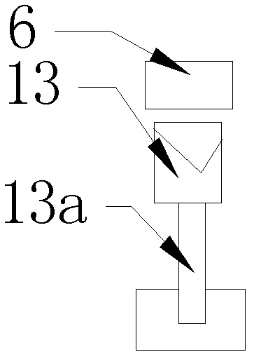
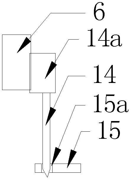

Image

  • Chip mounter
  • Chip mounter
  • Chip mounter

Examples


Embodiment Construction

[0019] The present invention will be further described through embodiment now in conjunction with accompanying drawing. like Figure 1-4 As shown, the main body includes X, Y, and Z-axis drive mechanisms 2, 3, and 16 respectively arranged on the frame 1, and a placement head 6, a conveyor belt, and a feeding device. The driving mechanism of material belt 15 is made of needle bar 14 and transmission is connected to needle bar 14 as the electric, pneumatic (air pressure) or hydraulic driver 15a of the driver of material belt; Needle bar 14 is corresponding to material belt 15 on the feeding device The belt hole 15a is connected to the placement head, driven by an electric, pneumatic or hydraulic driver 14a, and can be moved forward, backward, left, right and up and down through the placement head.

[0020] The feeding device is a feeding frame 9 detachably connected to the frame 1 through a connecting piece, corresponding to several feed bins 12 respectively arranged on the fee...


PUM


Abstract

The invention discloses a simply structured chip mounter with high work efficiency, high reliability, low manufacturing cost and small volume. The chip mounter comprises an integrated feeding frame, a material belt driving device, a two-segment type conveyor belt, a suction nozzle changing device and a circuit board supporting and balancing device, wherein the integrated feeding frame is composed of storage bins and corresponding grooves arranged on a frame body, the material belt driving device is composed of a needle bar, the suction nozzle changing device and the circuit board supporting and balancing device are respectively located under a chip mounting working surface, and the number of the storage bins and the number of the corresponding grooves are respectively 40.

Description

technical field [0001] The invention relates to a processing machine for circuit boards of electronic appliances, in particular to a placement machine for mounting circuit boards. Background technique [0002] The placement machine is a relatively modern production and processing device for telecommunication products. With the continuous development of the electronic industry technology, the placement machine has more and more types, the structure is more reasonable and mature, the function is more powerful and perfect, and the performance is more superior. reliable. Nevertheless, things are always developing, and there are always defects and deficiencies of one kind or another in existing placement machines. For example, the relatively mature and widely used placement machine has only one set of conveyor belts, and the circuit board is supported by two narrow belts at the front and rear, and the middle is empty. Although this structure is simple, it can only wait for one l...

Claims


Application Information

Patent Timeline
Patent Type & Authority Patents(China)
IPC IPC(8): H05K13/04H05K3/30
Inventor 曾贤敏蒋志坚
Owner JIANGXI WANSHEN MACHINERY
Learn More