
Method for operating a reciprocating piston engine and piston for a reciprocating piston engine

A reciprocating piston and engine technology, applied in the field of operating reciprocating piston engines and pistons for reciprocating piston engines, can solve the problems of optimized operation mode, impossibility, power loss, etc., achieve obvious power gain, and facilitate maintenance , Friction loss reduction effect

Active Publication Date: 2011-12-14
MAN DIESEL & TURBO FILIAL AF MAN DIESEL & TURBO SE TYSKLAND
View PDF9 Cites 6 Cited by
  • Summary
  • Abstract
  • Description
  • Claims
  • Application Information

AI Technical Summary

Problems solved by technology

However, the friction that occurs during operation and the resulting power loss increases with the number of piston rings
Therefore, this known device still can't realize optimal mode of operation to a great extent

Method used


Image

  • Method for operating a reciprocating piston engine and piston for a reciprocating piston engine
  • Method for operating a reciprocating piston engine and piston for a reciprocating piston engine

Examples


Embodiment Construction

[0020] The main field of application of the invention is reciprocating piston engines designed as large engines, in particular large two-stroke diesel engines such as are used in the drive of ships. The basic structure and mode of operation of such devices are known per se and therefore do not need to be described in detail in the present case.

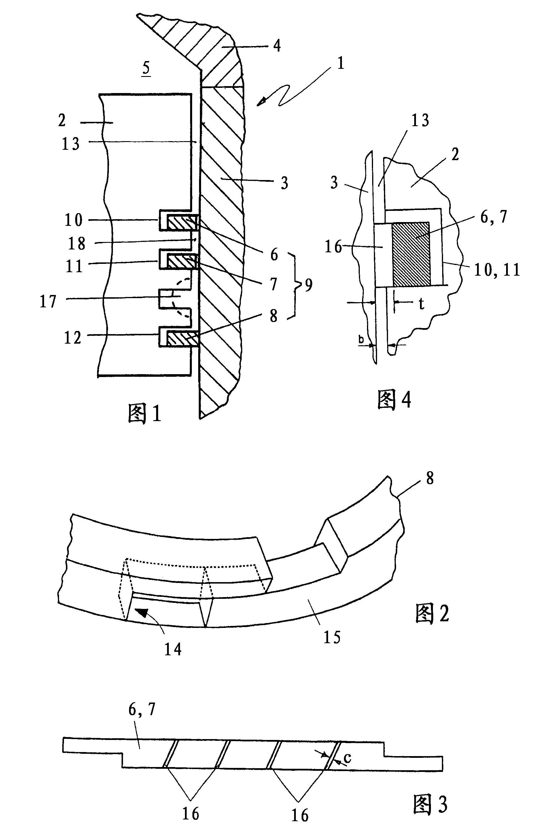
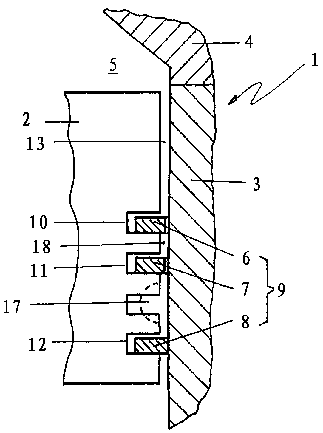
[0021] figure 1 The involved cylinder-piston assembly belongs to a two-stroke large diesel engine. The shown cylinder-piston assembly comprises a cylinder 1 and a piston 2 housed in the cylinder. The cylinder 1 comprises a surrounding cylinder liner 3 and a cylinder head 4 received thereon. A working chamber 5 is provided in the cylinder 1 , the lower boundary of which is formed by a vertically movable piston 2 guided in a cylinder liner 3 . During operation, the working chamber 5 is acted upon with a charge consisting mainly of air via an intake slot, not shown in detail, arranged in the lower region of the cylinder liner 3 , and ...


PUM


Abstract

The invention relates to a piston applied in a reciprocating piston type engine. The piston (2) defines a working chamber (5) and can move inside a cylinder sleeve (3). A piston ring group (9) is applied for covering a gap (13) between the piston and the cylinder sleeve. The piston ring group comprises a plurality of piston rings (6, 7, 8) arranged in a front-back manner and respectively equipped inside a corresponding piston ring groove (10, 11, 12) of the piston (2). The piston rings can be loaded by the air inside the working chamber. In this way, a significant decrease in power loss and a basic balance in the service lifetime of each piston ring are realized. The gap between the piston and the cylinder sleeve is sealed by one piston ring farthest away from the working chamber in an airtight way. Controllable leakage is allowed on piston rings (6, 7) in front of each piston ring arranged farthest away from the working chamber. The pressure of the leaked air is reduced by the expansion of at least one expansion chamber (17) before the air reaches the piston ring arranged farthest away from the working chamber.

Description

technical field [0001] The invention relates to a method for operating a reciprocating piston engine and a piston for such a reciprocating piston engine, in particular a piston for a large two-stroke diesel engine, which is arranged as a working chamber delimitation in the corresponding cylinder In the sleeve, wherein the gap between the piston and the cylinder liner is covered by a piston ring set, the piston ring set has a plurality of piston rings arranged in sequence, respectively arranged in the corresponding piston ring grooves of the piston, these piston rings The ring can be loaded with gas from the working chamber. Background technique [0002] In arrangements of this type which are common in practice, gas leakage is provided on all piston rings. For this purpose, slotted piston rings are generally used, the ends of which are spaced apart from one another so as to form a continuous gap from top to bottom, which gap forms a flow path for the leakage gas. However, t...

Claims


Application Information

Patent Timeline
Patent Type & Authority Applications(China)
IPC IPC(8): F02B75/02F02F3/02
CPCF16J3/042F02F3/00F02F5/00F16J9/00F16J9/068F16J9/10
Inventor C·L·费尔特
Owner MAN DIESEL & TURBO FILIAL AF MAN DIESEL & TURBO SE TYSKLAND
Learn More