
Method for realizing accurate oriented perforating by cable transmission

A technology of precise orientation and cable transmission, which is applied in the direction of mining fluid, earthwork drilling, wellbore/well components, etc., can solve the problems of long construction period, high resistance of wellhead rotating tubing, and impossibility of application. The effect of shortening the well occupation time and improving the construction efficiency

Active Publication Date: 2013-09-04
PETROCHINA CO LTD
View PDF1 Cites 3 Cited by
  • Summary
  • Abstract
  • Description
  • Claims
  • Application Information

AI Technical Summary

Problems solved by technology

This directional perforation method has two disadvantages: ①The resistance of the tubing to rotate at the wellhead is relatively large, and it cannot be applied when the maximum inclination angle exceeds 15°; ②The tubing transmission process is too complicated, the construction period is long, and the economic benefit is poor
This directional perforation method has two disadvantages: ①The radius of the wellbore is small, the torque provided by the deflector is small, the inclination angle is less than 30°, and the continuous length of the perforating gun is more than 10m, the positioning cannot be realized; ②The tubing transmission process is too complicated, Long construction period and poor economic benefits
For directional perforating wells in Changqing, the inclination angle of the oil layer section is generally less than 10°, but the maximum inclination angle of the whole well is generally 10-35°, and the continuous length of the perforating gun is generally 12-20m. Oriented perforation with central weight can not meet the needs of directional perforation in Changqing Oilfield

Method used


Image

  • Method for realizing accurate oriented perforating by cable transmission
  • Method for realizing accurate oriented perforating by cable transmission
  • Method for realizing accurate oriented perforating by cable transmission

Examples


Embodiment 1

[0062] Embodiment 1: Taking the method of realizing precise directional perforation in a well using cable transmission as an example, the present invention will be further described in detail.

[0063] The directional perforation construction process of Well A in Changqing Oilfield.

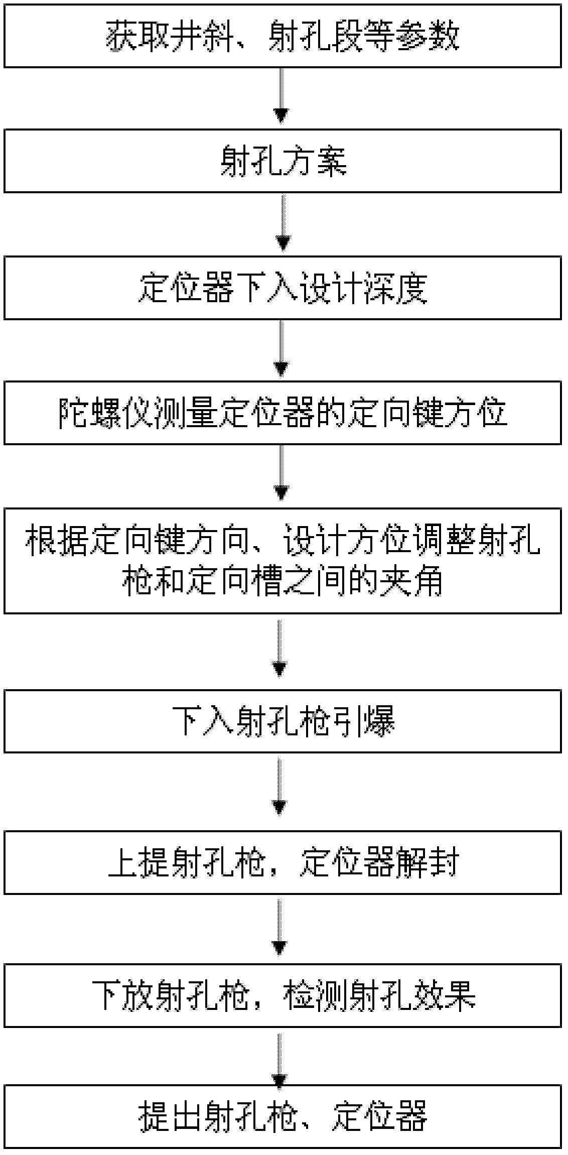
[0064] 1. First, collect parameters such as well deviation and perforation section:

[0065] 2. Azimuth perforation construction design

[0066] (1) Positioning support device:

[0067] It adopts 51 / 2" positioning support device, the maximum outer diameter is 114mm, the length is 1000mm, and the shearing force of the piston shear pin is 8T.

[0068] (2) Azimuth measuring instruments:

[0069] Adopt HKTL-46 gyro azimuth measuring instrument, the maximum outer diameter is 46mm, and the maximum outer diameter of the centralizing ring is 102mm.

[0070] (3) Azimuth perforating gun:

[0071] a. The outer diameter of the positioning perforator is 102mm, the maximum outer diameter of the joint is 1...


PUM


Abstract

The invention relates to a method for realizing accurate oriented perforating by cable transmission, and is applied to the orientation perforating of a casing pipe well of an oil field during well completion. The method comprises the following steps of: sinking a positioning device and setting; sinking a gyro inclinometer, and measuring the accurate orientation of a guiding key on the upper part in the positioning device; sinking a perforating gun, orienting accurately, and perforating; and lifting the positioning device and the perforating gun to realize accurate oriented perforating construction by the cable transmission. The method has the advantages that: the oriented perforating of a well of which the maximum well oblique angle of the whole well exceeds 15 degrees and a well oblique angle of a perforating section is less than 30 degrees is realized; the period of perforating construction is reduced to 8 hours from 30 hours for the oriented perforating by oil pipe transmission, and the construction efficiency is improved; and the oil pipe transmission is replaced by the cable transmission, so the labor intensity is reduced.

Description

technical field [0001] The invention relates to the technical field of oilfield well completion, in particular to a method for azimuth perforation in cased well completion, which is a method for realizing directional perforation in oil wells with a well inclination angle between 15° and 30°. Background technique [0002] There are two existing directional perforation techniques: when the maximum inclination angle of the whole well is less than 15°, directional perforation is realized through tubing transmission, gyro inclinometer measurement of azimuth, ground rotating tubing, etc. directional perforation is achieved through tubing transmission, eccentric weight orientation, etc. [0003] The directional perforating technology for vertical wells is relatively mature. The principle is to measure the direction of the downhole perforating gun through the gyro inclinometer, and rotate the tubing on the ground to drive the perforating gun to the designed position. The main steps...

Claims


Application Information

Patent Timeline
Patent Type & Authority Patents(China)
IPC IPC(8): E21B43/116
Inventor 唐梅荣赵振峰李宪文赵文马兵王晓东杨晓刚李转红樊凤玲王蓓
Owner PETROCHINA CO LTD
Learn More