
Vibration rammer with horizontal vibration function

A vibratory rammer and functional technology, applied in the field of vibratory rammers, can solve the defects of safety and work efficiency, can not solve the problems of vibratory rammer horizontal clamping, vibration amplitude disorder, etc., and achieve the effect of large effective working range

Inactive Publication Date: 2011-12-14
建研机械检验检测(北京)有限公司 +1
View PDF5 Cites 5 Cited by
  • Summary
  • Abstract
  • Description
  • Claims
  • Application Information

AI Technical Summary

Problems solved by technology

The existing plate vibrating equipment can only vibrate in the vertical direction, and cannot vibrate in the horizontal direction. The first reason is that it cannot solve the problem of horizontal clamping of the vibrating rammer and the vibration at any height involved; During the vibration process, the direction of gravity is inconsistent with the direction of vibration, which will cause the vibration amplitude to be disordered; thirdly, in the construction, the wall usually has a certain height. The traditional method is to move the operator and the vibration equipment to the top of the wall for operation. This has great disadvantages in terms of safety and work efficiency.

Method used


Image

  • Vibration rammer with horizontal vibration function
  • Vibration rammer with horizontal vibration function
  • Vibration rammer with horizontal vibration function

Examples


Embodiment Construction

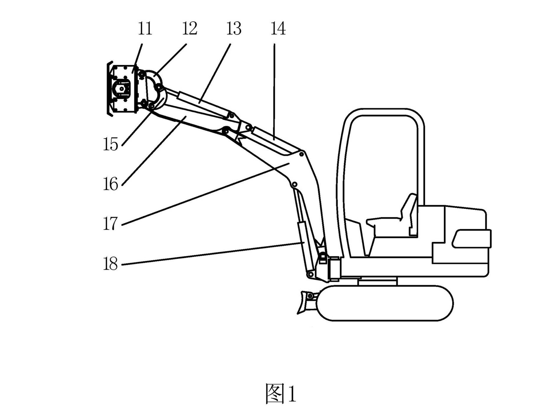
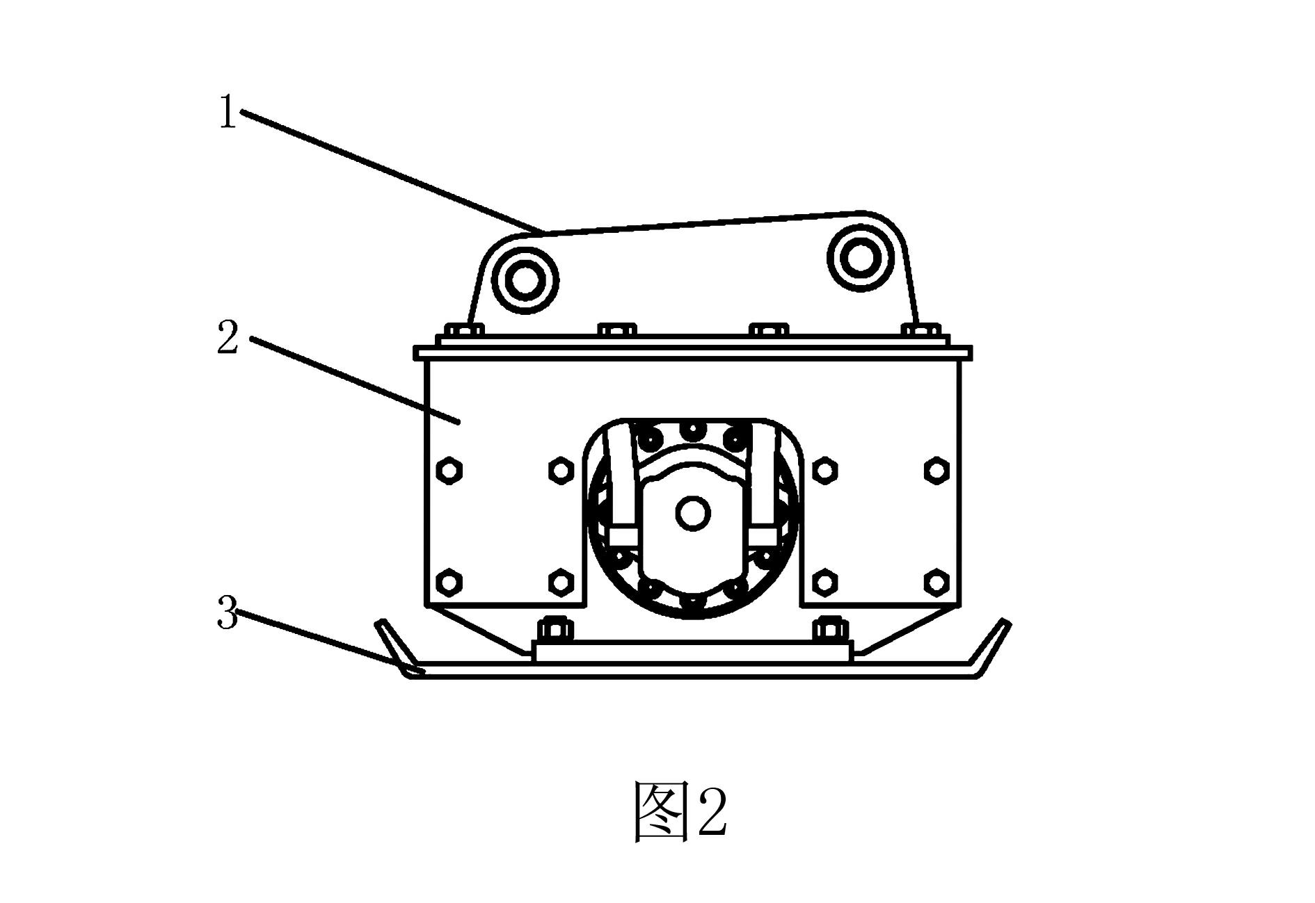
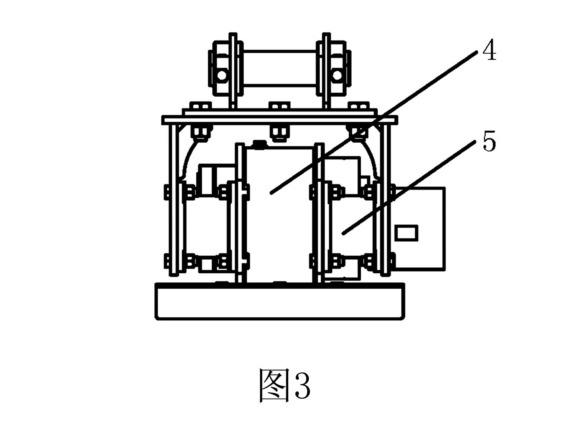
[0017] like figure 1 As shown, the vibration rammer with horizontal vibration function of the present invention includes a hydraulic excavator. The vibrating rammer with horizontal vibration function utilizes the hinge point cylinder 13, arm cylinder 14, and boom cylinder 18 of the hydraulic excavator to control the boom 17 and arm 16 to change the working position, as well as the rocker 15 and connecting rod 12. The technology that the connecting hinge point can change the position achieves the purpose of manipulating and controlling the vertical and horizontal vibration positions of the vibratory rammer with the horizontal vibration function. The above-mentioned accessories of the hydraulic excavator are used as the clamping device of the vibratory rammer with the function of horizontal vibration, so as to achieve the purpose of clamping and manipulating the vibratory rammer with the function of horizontal vibration for vibratory compaction under various conditions.

[0018...


PUM


Abstract

A vibrating rammer with a horizontal vibration function is composed of a connecting frame and a supporting frame to form a casing, a vibration exciter is installed in the casing through a vibration-damping rubber block, and a tamping plate is installed on the lower part of the casing. The vibration exciter is composed of an output main shaft installed in the tamper shell through a stop bearing, the output main shaft is connected with a hydraulic motor, and a polarizing block is arranged on the output main shaft. The connecting frame is connected to the hydraulic excavator through sticks and connecting rods. The vibratory rammer with horizontal vibration function has a larger working range and vertical vibration capability. During the construction of raw earth buildings, the defects of low safety and low work efficiency of operators working at high places are overcome. The vibration rammer provided by the invention has the function of horizontal vibration, has simple structure and easy operation, and can perform vertical and horizontal compaction work.

Description

technical field [0001] The invention relates to a flat plate vibrating rammer, in particular to a vibrating rammer with a horizontal vibrating function which uses a clamping device to vibrate. Background technique [0002] In the construction of raw-earth houses and raw-earth walls, it is necessary to use a vibrating rammer to vibrate the top and side surfaces of the wall in order to repair small cracks on the wall and tamp the wall. The existing plate vibrating equipment can only vibrate in the vertical direction, and cannot vibrate in the horizontal direction. The first reason is that it cannot solve the problem of horizontal clamping of the vibrating rammer and the vibration at any height involved; During the vibration process, the direction of gravity is inconsistent with the direction of vibration, which will cause the vibration amplitude to be disordered; thirdly, in the construction, the wall usually has a certain height. The traditional method is to move the operator...

Claims


Application Information

Patent Timeline
Patent Type & Authority Applications(China)
IPC IPC(8): E04G21/06
Inventor 李杨虞洪
Owner 建研机械检验检测(北京)有限公司
Learn More