Winding machine

A winder, mechanical technology, applied in thin material handling, conveying filamentous materials, transportation and packaging, etc., which can solve the problems of broken yarn winding and damage to the installation part of the contact roller.

Active Publication Date: 2011-12-07
TMT MACHINERY INC
View PDF4 Cites 12 Cited by
  • Summary
  • Abstract
  • Description
  • Claims
  • Application Information

AI Technical Summary

Problems solved by technology

[0006] However, as in Patent Document 1, by detecting the contact pressure of each bobbin and changing the pressure applied to the touch roller by the adjustment cylinder according to the detection result, thereby tilting the touch roller, if the yarn If the adjusting cylinder is damaged during the winding process, the pressure exerted by the adjusting cylinder on the touch roller changes rapidly. Vibration occurs on the touch roller, causing damage to the mounting part of the touch roller, etc.

Method used


Image

  • Winding machine
  • Winding machine
  • Winding machine

Examples


Embodiment Construction

[0038] Hereinafter, preferred embodiments of the present invention will be described.

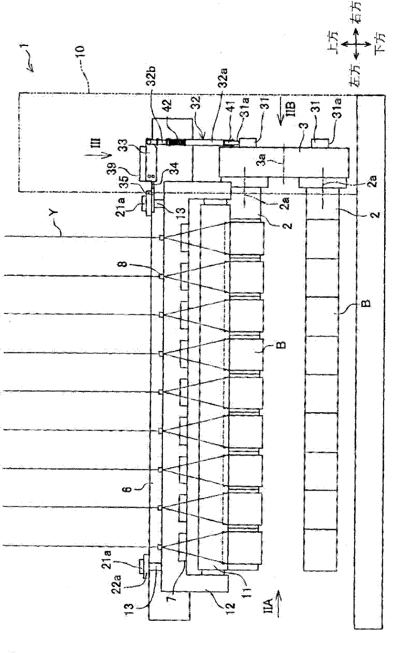
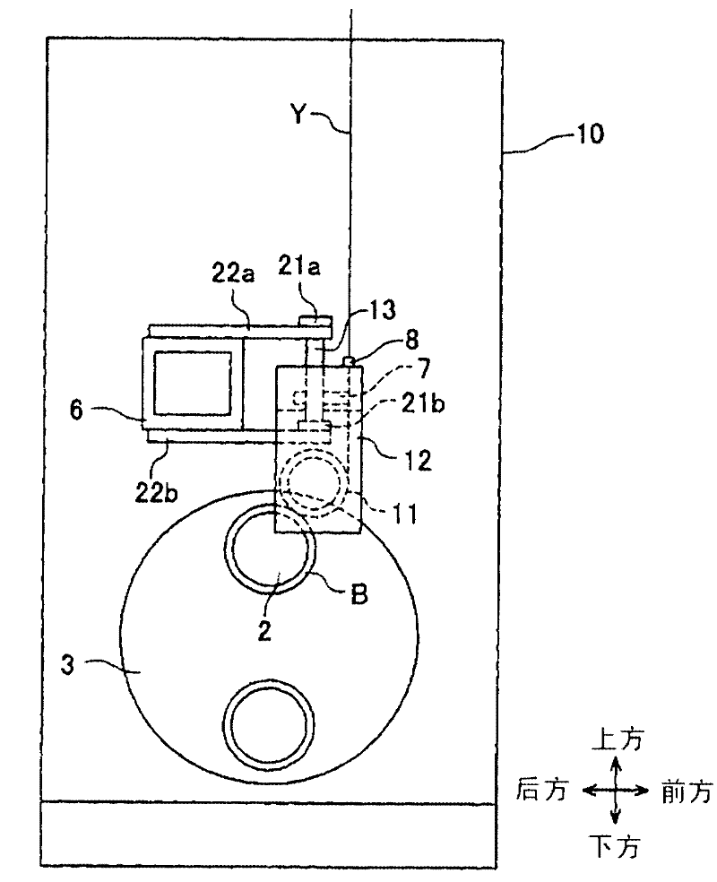
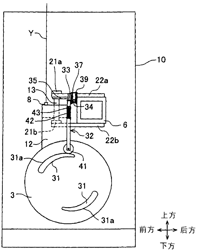
[0039] figure 1 It is the figure which looked at the winding machine concerning this embodiment from the front. Figure 2A It is viewed from the direction of arrow IIA figure 1 diagram. Figure 2B It is viewed from the direction of arrow IIB figure 1 diagram. Figure 3A It is viewed from the direction of arrow III figure 1 diagram. Figure 3B From Figure 3A The figure which removed the attachment member 22a and the swing shaft 36 mentioned later. Figure 4 yes Figure 3A Sectional view of line IV-IV. Among them, in figure 1 In , a part of the body 10 of the winding machine 1 is shown with a two-dot chain line, and the inside of the part indicated with a two-dot chain line is shown. Figure 3B In the figure, the position of the mounting member 22a is indicated by a two-dot chain line in order to make the positional relationship of each member easy to understand. In addition, in ...


PUM


Abstract

An object of the present invention is to provide a winder in which improper winding of yarns and the breakdown of portions around the contact roller hardly occur even if a tilt unit by which the contact roller is tilted is broken. In a winder 1, as an amount of yarns Y wound onto bobbins B increases, a turret table 3 rotates in the direction in which a bobbin holder 2 moves away from a contact roller 11. A tilt mechanism 5 transfers, by a cam 31, a cam rod 32, a force multiplying arm 33, a tie rod 34, and a tilt arm 35, the rotation of the turret table 3 to a guide shaft 13 elevatably supports a supporting member 12, so as to tilt the guide shaft 13. As a result, as the amount of the yarns Y wound onto the bobbins B attached to the bobbin holder 2 is increased and the bobbin holder 2 is warped, the contact roller 11 supported by the supporting member 12 is tilted.

Description

technical field [0001] The invention relates to a winding machine for winding yarn onto bobbins. Background technique [0002] In the winding machine described in Patent Document 1, contact rollers (touch rollers) extending parallel to the bobbin holder are brought into contact with a plurality of bobbins mounted on the bobbin holder supported by a cantilever. The rollers apply contact pressure to the bobbin while winding the yarn onto the bobbin. [0003] Here, in such a winder, as the amount of yarn wound onto the bobbin by the contact roller increases, the bobbin holder is closer to the front end portion farther from the supported portion due to the weight of the yarn. Flex downward. [0004] Therefore, in the winding machine described in Patent Document 1, the contact pressure of each bobbin is detected, and the adjustment cylinder is extended or retracted according to the detection result, thereby changing the pressure applied to the contact roller, and the contact pr...

Claims


Application Information

Patent Timeline
Patent Type & Authority Applications(China)
IPC IPC(8): B65H54/52
CPCB65H67/048B65H54/52B65H2701/31
Inventor 杉山研志
Owner TMT MACHINERY INC
Why Eureka
Try Eureka