
Hose fitting assembly station

A technology of hose joints and assembly tables, which is applied in the direction of hand-held tools and manufacturing tools, which can solve the problems of easy leakage, tearing, and unsuitability for assembly line production at the end of the joint, and achieve the effect of stable advance and retreat, and accurate direction

Inactive Publication Date: 2011-12-07
ZHEJIANG BOSHITE MECHANICAL CO LTD
View PDF5 Cites 15 Cited by
  • Summary
  • Abstract
  • Description
  • Claims
  • Application Information

AI Technical Summary

Problems solved by technology

[0002] The oil, water, gas and other hoses that are widely used in various mechanical equipment need to be installed with joints. The earliest tools used were: reformed pliers, clamping table ax pliers and a plastic hammer. This kind of tooling There are many disadvantages: the pipe body is easy to pinch, scratch, collapse and tear, the end of the joint is easy to leak, the efficiency of hand tools is low, and it is not suitable for assembly line production

Method used


Image

  • Hose fitting assembly station
  • Hose fitting assembly station
  • Hose fitting assembly station

Examples


Embodiment 1

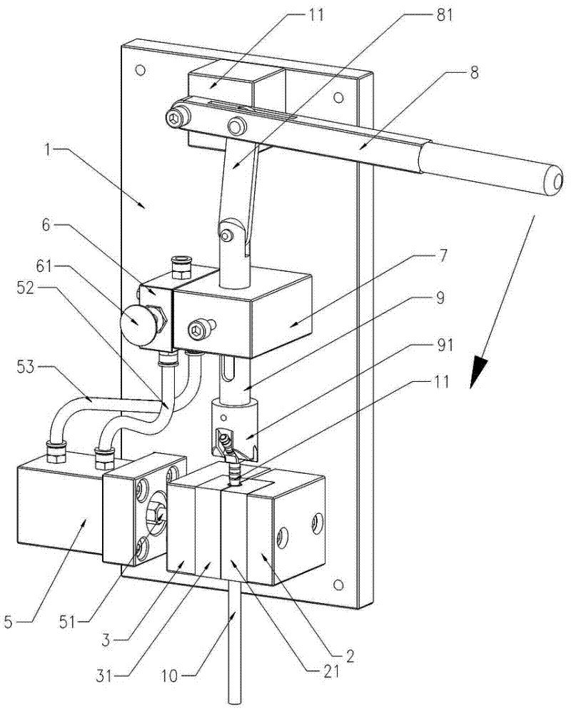
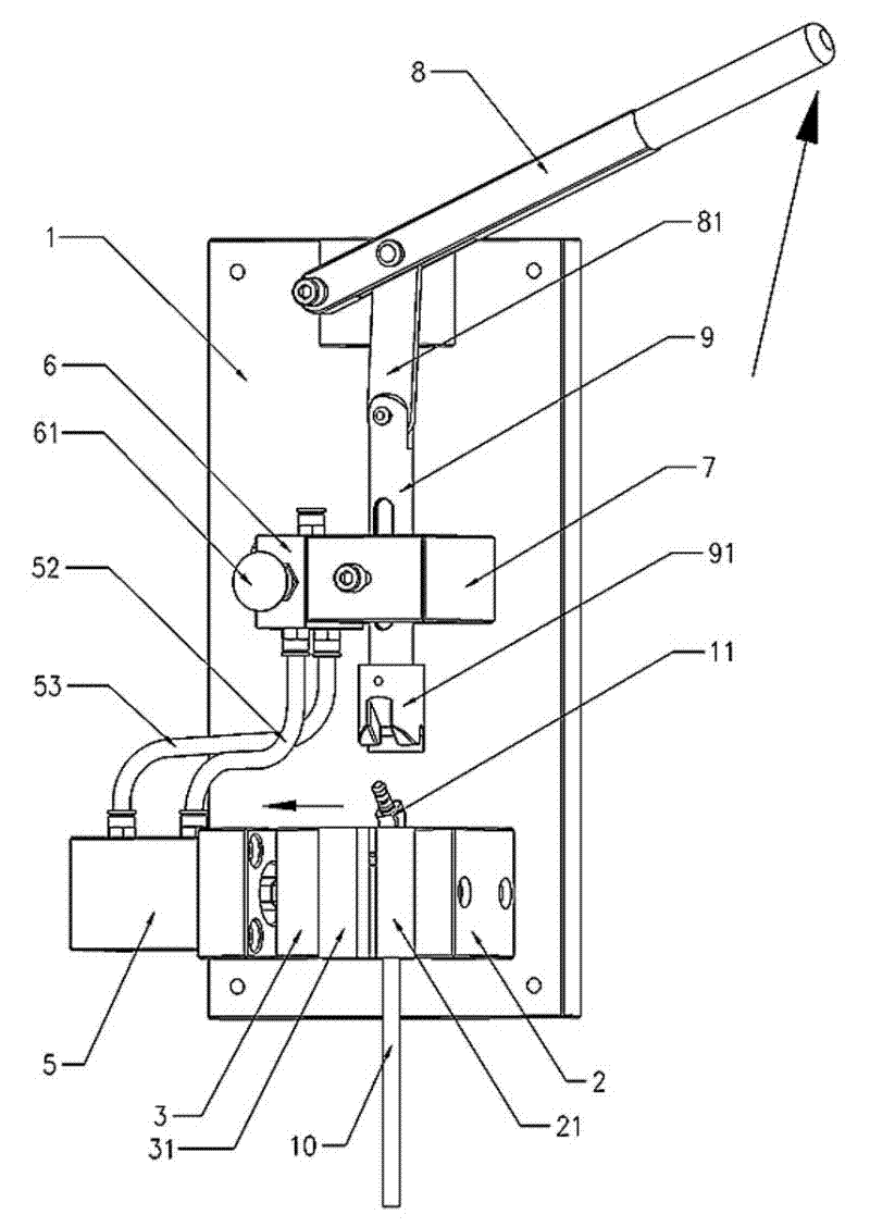
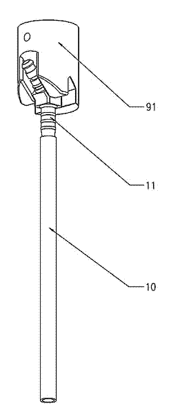
[0029] The structure of the hose joint assembly table is as follows: Figure 1 to Figure 5 As shown, the operation process is as follows: the operator places the rubber hose 10 in the groove of the fixed block 2, the end surface of the rubber hose 10 is flush with the side of the fixed block 2, and presses the button 61 of the two-way valve 6 to let the high-pressure air flow from the cylinder The rear air inlet 53 of 5 is input, and the piston push rod 51 is pushed forward together with the sliding clamping block 3, and the rubber hose 10 is clamped and fixed with the fixing block 2, and a pipe joint 11 is held in the left hand and placed on the top of the punch 91, and the right hand plate Move the handle 8, press the push rod 9 together with the punch 91 to the pipe joint 11 through the connecting piece 81, force the pipe joint 11 into the inner wall of the rubber hose 10, and use the interference fit to tightly fix the two together. Press the button 61 of the two-way valve...

Embodiment 2

[0031] Embodiment 2: The basic structure is the same as that of Embodiment 1, if the assembly structure is relatively simple straight pipe joint 112, such as Figure 6 Shown; Then the punch 91 that uses among the embodiment 1 is changed into the cylindrical punch 92 and gets final product, and operation method is identical with embodiment 1.


PUM


Abstract

The hose joint assembly platform is fixed with a fixed block, cylinder, two-way valve, and support plate on the bottom plate; the two-way valve controls the advance and retreat of the piston push rod through the intake pipe; the sliding clamping block is pulled by the piston push rod. The fixed block is closed and separated; soft cushion blocks are respectively set on the mating surfaces of the fixed block and the sliding clamping block, and the corresponding parts have semicircular grooves, which are convenient for clamping the hose; the push-pull handle connects the push rod together with the punch Press against the pipe joint, rigidly insert the pipe joint into the inner wall of the rubber hose, and use the interference fit to fix the two tightly together. Equipping corresponding series of punches for pipe joints of different shapes and sizes can expand the scope of application, convenient and quick assembly, good sealing performance of joints, and high production efficiency.

Description

technical field [0001] The invention relates to a processing equipment for connection of oil, water, gas and other hose pipes, in particular to a hose joint assembly platform. Background technique [0002] The oil, water, gas and other hoses that are widely used in various mechanical equipment need to be installed with joints. The earliest tools used were: reformed pliers, clamping table ax pliers and a plastic hammer. This kind of tooling There are many disadvantages: the pipe body is easy to pinch, scratch, collapse and tear, the end of the joint is easy to leak, the efficiency of hand tools is low, and it is not suitable for assembly line production. [0003] Based on the above understanding, our company has carried out several technical transformations according to the operation characteristics of the pipe joints, gradually improving from semi-automatic fixtures to today's hose joint assembly stations, and this case came about. Contents of the invention [0004] The o...

Claims


Application Information

Patent Timeline
IPC IPC(8): B25B27/00
Inventor 龚国京冯波傅海松
Owner ZHEJIANG BOSHITE MECHANICAL CO LTD
Learn More