
Scr denitrification process and device for high dust flue gas

A technology of a dust removal device and an SCR reactor, applied in the field of flue gas purification, can solve the problems of large losses, increase operating costs, shorten the service life of catalysts, etc., and achieve the effect of reducing the probability of blockage, prolonging the life of catalysts, and reducing the amount of catalysts used.

Inactive Publication Date: 2011-12-07
CPI YUANDA ENVIRONMENTAL PROTECTION ENG
View PDF4 Cites 9 Cited by
  • Summary
  • Abstract
  • Description
  • Claims
  • Application Information

AI Technical Summary

Problems solved by technology

[0005] (1) Due to the high-dust arrangement and no dust removal, the dust content in the flue gas is high, and it is easy to block the catalyst. If the catalyst is blocked, the furnace must be shut down, causing huge losses and increasing operating costs;
[0006] (2) The dust concentration is high, and the NH leaked from the denitrification reaction 3 with SO 3 and H 2 O will generate substances such as ammonium bisulfate (ABS), which has a high viscosity and will cause dust to accumulate on the surface of the air preheater, causing contamination and corrosion of the air preheater, and blockage of the air preheater , increase the cleaning frequency of the air preheater and increase operating costs;
[0007] (3) In order to reduce the probability of catalyst clogging, it is generally necessary to select a catalyst with a large pore size, which will result in a larger volume of the catalyst and increase the investment cost of the SCR project;
[0008] (4) Dust contains calcium oxide, alkali metal and other substances harmful to the catalyst, which can easily cause catalyst wear and poisoning, shorten the service life of the catalyst, increase operating costs, and reduce the stability and reliability of the device

Method used


Image

  • Scr denitrification process and device for high dust flue gas
  • Scr denitrification process and device for high dust flue gas

Examples


Embodiment Construction

[0023] Hereinafter, preferred embodiments of the present invention will be described in detail with reference to the accompanying drawings.

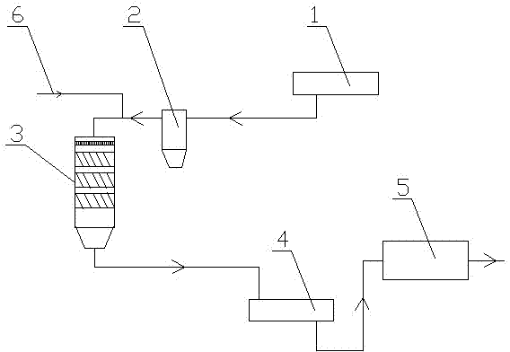
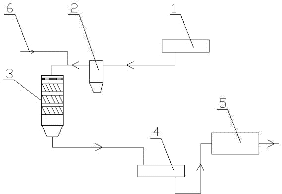
[0024] figure 1 It is a process flow diagram of the present invention, as shown in the figure, the SCR denitration device for high dust flue gas of the present invention includes a boiler economizer 1, a dust removal device 2 and an SCR reactor 3, and the boiler economizer 1 The flue gas outlet communicates with the inlet flue of the SCR reactor 3 through the dust removal device 2 .

[0025] In the present embodiment, the dust removal device 2 is a gravity dust collector; although common dust removal devices such as centrifugal dust removal (such as cyclone separator) or filter dust removal can also achieve the effect of the present invention, but with these dust removal devices, the flue gas The pressure loss is very large, and the wear is serious when dealing with high-concentration or abrasive dust; while using a gravity dust collect...


PUM


Abstract

The invention discloses an SCR denitrification process and device for coping with high dust flue gas, including a boiler economizer, a dust removal device and an SCR reactor, the flue gas outlet of the boiler economizer passes through the dust removal device and the SCR reactor inlet The flue is connected; the present invention adopts a low-dust arrangement method, and the flue gas drawn from the boiler economizer is subjected to dust removal treatment before entering the SCR reactor, which can reduce the amount of catalyst, reduce the dust content in the flue gas, and especially remove The large particles of dust in the flue gas reduce the blockage of the denitrification catalyst by the dust in the flue gas, and the poisoning of the catalyst by harmful substances in the dust, which improves the service life of the catalyst.

Description

technical field [0001] The invention belongs to the technical field of flue gas purification, and in particular relates to an SCR flue gas denitrification process and device. Background technique [0002] The existing SCR flue gas denitrification process mostly adopts high-dust arrangement, that is, the SCR reactor is arranged between the boiler economizer and the air preheater, and the flue gas drawn from the boiler economizer passes through the SCR reactor and then enters the air preheater. heater. It is the most common arrangement in power plants. The high-dust arrangement has the following characteristics: high dust content, SO X The concentration is higher. [0003] As a large coal-producing country, China has great differences in coal quality in different regions. Even in the same region, the coal quality of different coal types is also very different. In the process of data collection and sorting, we found that in order to meet the heat generation requirements and...

Claims


Application Information

Patent Timeline
Patent Type & Authority Applications(China)
IPC IPC(8): B01D53/90B01D53/56B01D45/02
Inventor 杜云贵洪燕聂华吴其荣
Owner CPI YUANDA ENVIRONMENTAL PROTECTION ENG
Learn More