Roller bearing for two components that can be at least axially moved toward one another, particularly for transmission shifting elements
A technology of rolling bearings and transmissions, which is applied in the direction of linear motion bearings, shafts and bearings, rotating parts that resist centrifugal force, etc. It can solve the problems of inseparable maintenance and achieve the effect of flexible and accurate detection
- Summary
- Abstract
- Description
- Claims
- Application Information
AI Technical Summary
Problems solved by technology
Method used
Image
Examples
Embodiment Construction
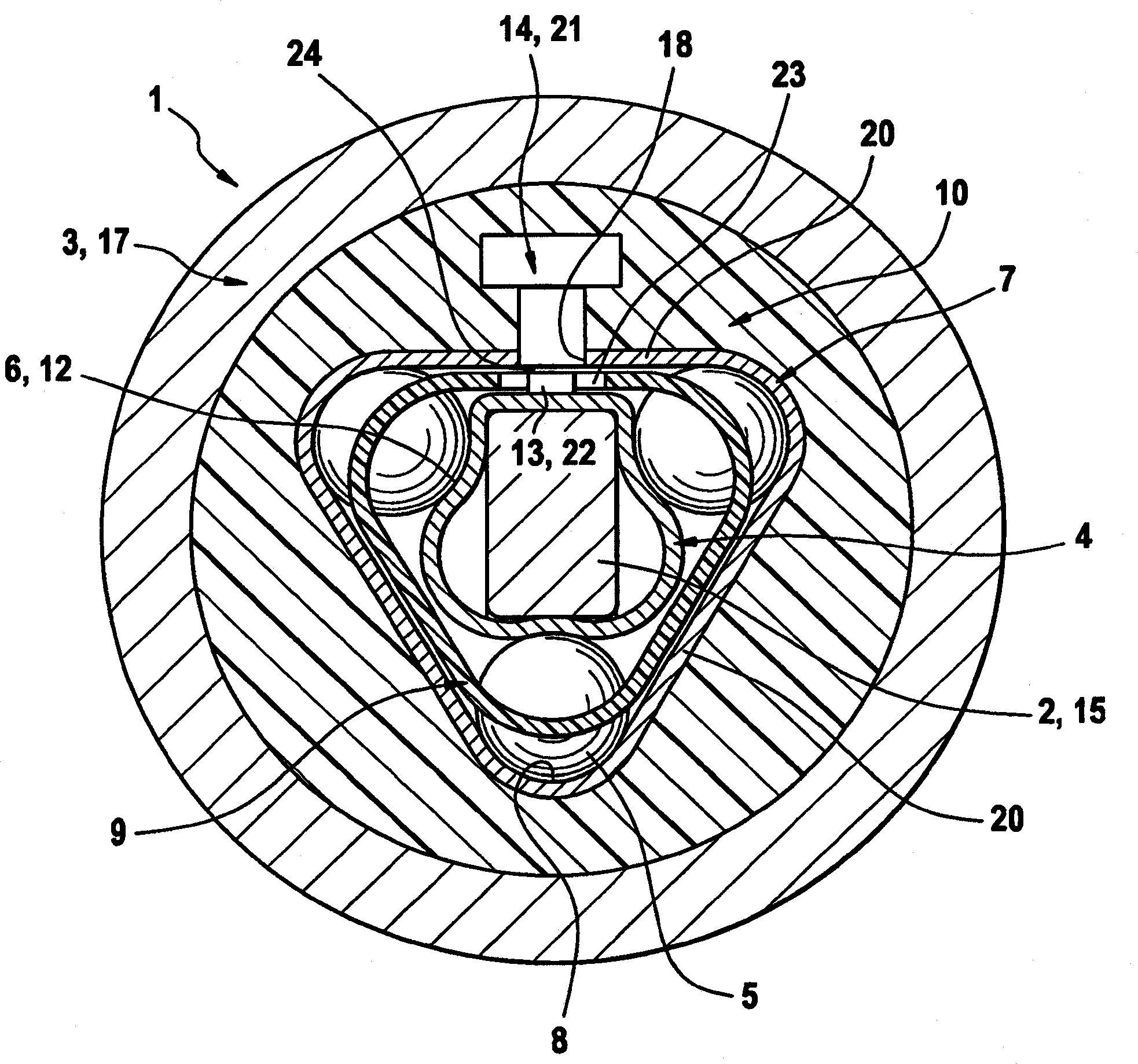
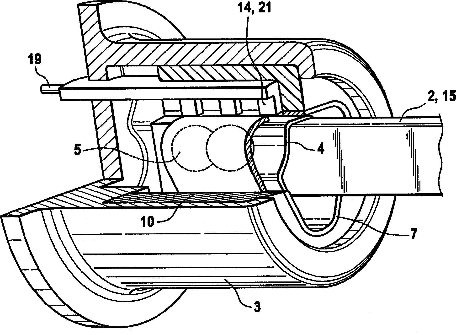
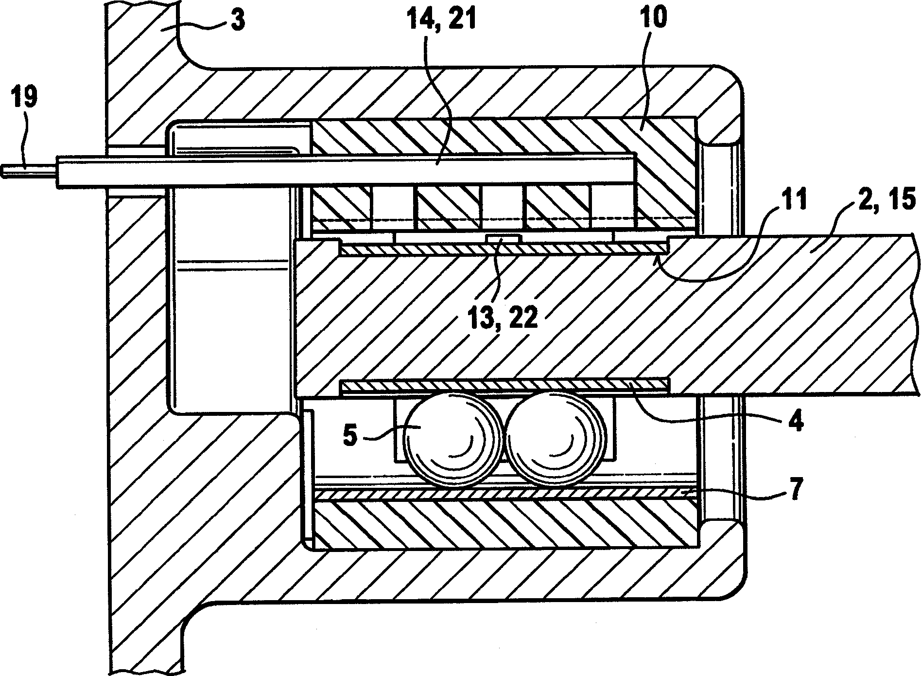
[0028] figure 1The schematic diagram of the figure shows a cross-section of an embodiment of a rolling bearing 1 according to the invention, which comprises a first part 2 as a shift fork shaft 15 with a rectangular cross-section, which can be axially Mounted in a movable manner (that is to say perpendicular to the drawing plane) in the second part 3 as transmission housing 17 . On the outer circumference of the shift fork shaft 15 is arranged the inner sleeve 4 as a sheet metal profile, which is used as an internal guide for the rolling elements 5 which are only schematically shown in the drawings, and these rolling elements are in the present embodiment respectively Formed by spheres. The inner sleeve 4 has three guide sections 6 distributed over the circumference, which extend axially and have a circular section in cross-section. The radius of the circular segment corresponds to the radius of the rolling elements 5 so that they are enclosed and guided over a defined area....
PUM
 Abstract
Description
Claims
Application Information
 - R&D
- Intellectual Property
- Life Sciences
- Materials
- Tech Scout
- Unparalleled Data Quality
- Higher Quality Content
- 60% Fewer Hallucinations
Browse by: Latest US Patents, China's latest patents, Technical Efficacy Thesaurus, Application Domain, Technology Topic, Popular Technical Reports.
© 2025 PatSnap. All rights reserved.Legal|Privacy policy|Modern Slavery Act Transparency Statement|Sitemap|About US| Contact US: help@patsnap.com


