
Dispersion compensator

A technology of dispersion compensator and optical circulator, which is applied in the field of optical communication and can solve the problems of increasing the volume of the device

Inactive Publication Date: 2011-11-23
O NET COMM (SHENZHEN) LTD
View PDF6 Cites 0 Cited by
  • Summary
  • Abstract
  • Description
  • Claims
  • Application Information

AI Technical Summary

Problems solved by technology

The disadvantage of this solution is that in order to achieve more broadband requirements, it is necessary to increase the number or length of multiple 1 / 4 wave plates, PBS prisms, and etalons, which increases the volume of the device to a certain extent.

Method used


Image

  • Dispersion compensator
  • Dispersion compensator
  • Dispersion compensator

Examples


Embodiment Construction

[0018] The working principle of a dispersion compensator of the present invention will be further described below in conjunction with the accompanying drawings.

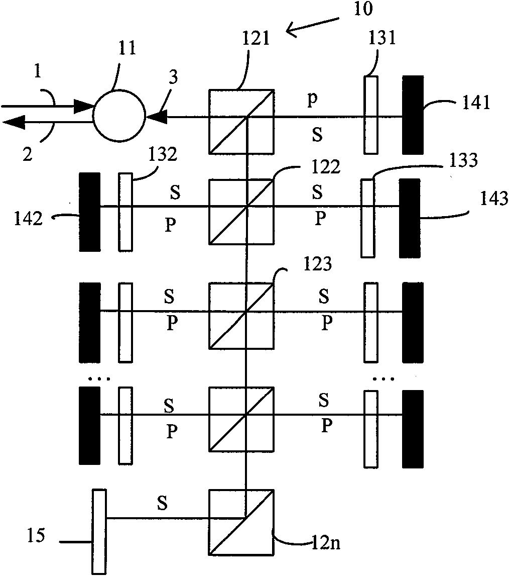
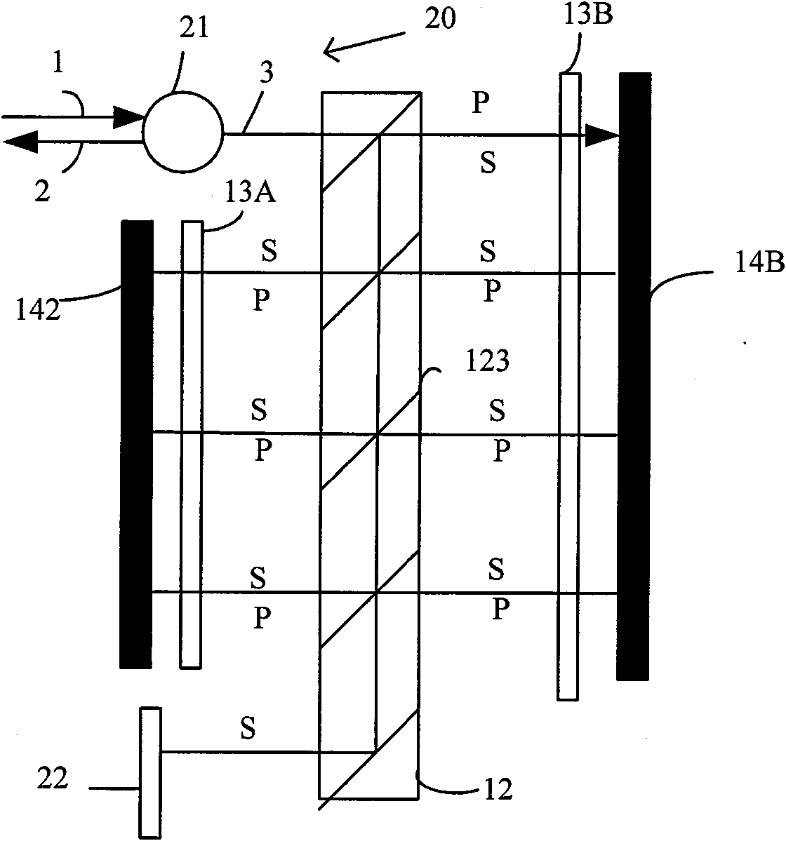
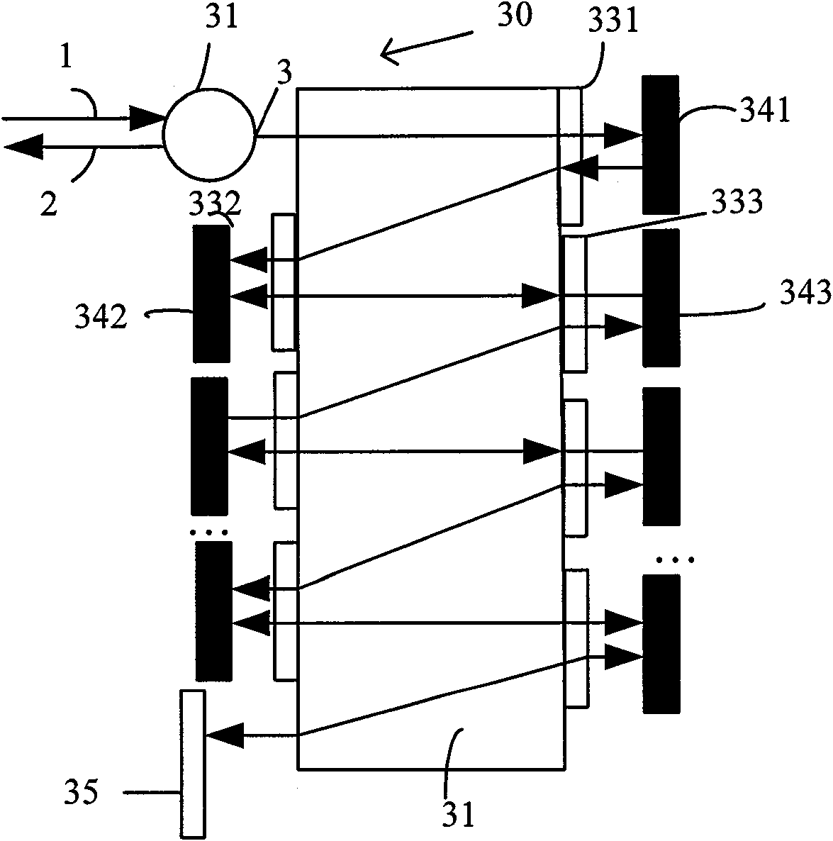
[0019] figure 1 It is a schematic diagram of the structure of the first embodiment of a dispersion compensator of the present invention, such as figure 1 As shown: the dispersion compensator 10 includes multiple sets of PBS prisms, 1 / 4 wave plates, etalon elements (Etalon), a reflector and an optical circulator, the splitting plane of the PBS prism is set at 45°, and Configured to transmit P-polarized light and reflect S-polarized light. Such as figure 1 As shown: the P-polarized light beam is incident through the first port 1 of the optical circulator 11, is transmitted to the first PBS prism 121 through the third port 3, enters the first standard element 141 through the first 1 / 4 wave plate 131, and is transmitted from the The light reflected back by the first etalon element 141 passes through the first 1 / 4 wave...


PUM


Abstract

The invention provides a dispersion compensator, which comprises a light guide component, two groups of polarization change component arrays and two groups of etalon component arrays. The dispersion compensator further comprises a reflecting mirror and an optical circulator. A polarized beam L is incident from a first port of the optical circulator, transmitted to the light guide component by a third port and incident into a first etalon component by a first polarization change component; light reflected from the first etalon component is changed into a polarized beam L1 vertical to the incident beam L after passing through the first polarization change component; the beam L1 is incident to the light guide component again and guided to a second polarization change component and a second etalon component after being shifted for a certain distance; and the light is regularly reciprocally reflected and propagated according to the light path until being reflected back to the light guide component by the reflecting mirror after passing through the light guide component, transmitted reversely by the light path and output by a second port. The dispersion compensator has a compacter and more miniature structure at the same time of meeting bandwidths in a larger range.

Description

technical field [0001] The invention belongs to the field of optical communication, and in particular relates to a dispersion compensator. Background technique [0002] The light propagating in the optical network usually suffers from chromatic dispersion (chromatic dispersion) or polarization mode dispersion (PMD). These dispersions will cause distortion of the optical signal waveform. coarse), correct data exchange cannot be performed. Since the PMD varies randomly due to the influence of the fiber laying condition and the external environment, the communication quality is degraded. In particular, the higher the speed, the easier it is to be affected by PMD, which is also the main reason for the degradation of the communication quality of the 100Gbps system. [0003] The basic optical element used in the dispersion compensation module is the GT (Gires-Tournois) etalon, which is essentially an all-pass filter, that is, all wavelength signals are fully reflected, and its r...

Claims


Application Information

Patent Timeline
Patent Type & Authority Applications(China)
IPC IPC(8): H04B10/18G02B27/28H04B10/2513
CPCH04B10/25133G02B6/29392G02B6/278
Inventor 王则钦陈彬谢红
Owner O NET COMM (SHENZHEN) LTD
Learn More