Inverter device and drive unit using the same
An inverter and radiator technology, applied in the field of drive units and inverter devices, can solve problems such as temperature rise, failure or failure of power components, reduce wiring impedance, reduce power loss, and shorten wiring distance. Effect
- Summary
- Abstract
- Description
- Claims
- Application Information
AI Technical Summary
Problems solved by technology
Method used
Image

Examples
no. 1 approach
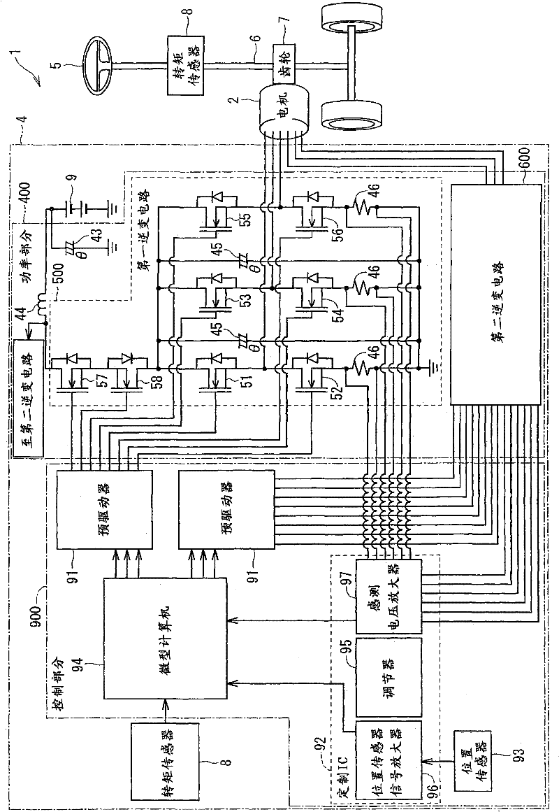
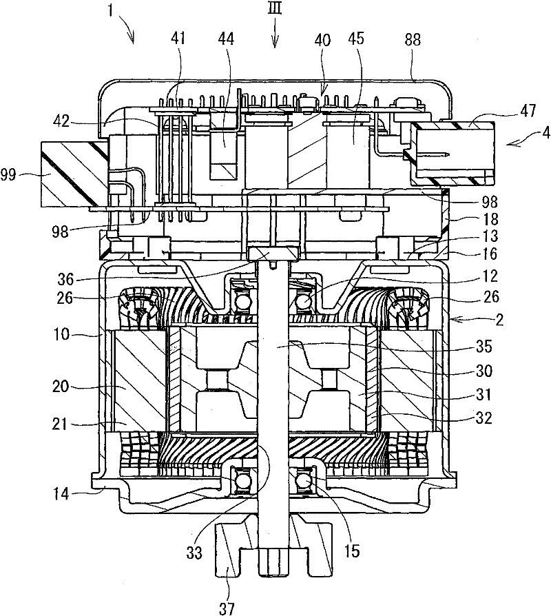
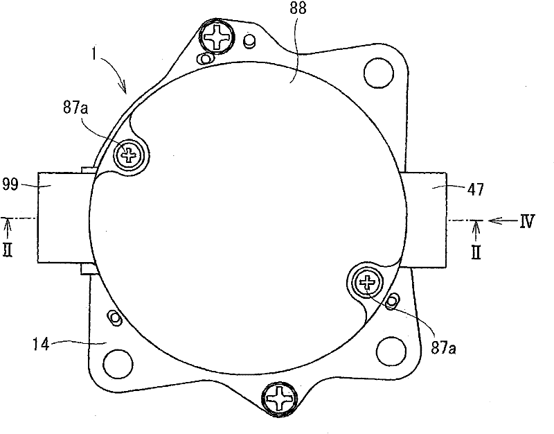
[0056] Figures 1 to 18 An inverter device and a drive unit using the inverter device according to a first embodiment of the present invention are shown. The drive unit 1 according to the present embodiment is applied to an electric power steering system. The drive unit 1 has an electric motor 2 and an inverter device 4 . The inverter device 4 includes a control board assembly 90, a heat sink 80, a plurality of power elements mounted on the heat sink 80, a power substrate assembly 40, and the like. The control board assembly 90 corresponds to a control wiring portion according to the present invention. The power substrate assembly 40 corresponds to a power wiring portion according to the present invention.
[0057] First, refer to figure 1 Describes the electrical structure of the electric power steering system. The electrical configurations described below are generally also used in subsequent embodiments. Such as figure 1 As shown, the drive unit 1 generates torque in...
no. 2 approach
[0114] Next, refer to Figures 19 to 21 An inverter device according to a second embodiment of the present invention will be described. The inverter device 3 according to the second embodiment is applied to a single drive unit system. The upper arm unit 50 including the power elements 51 - 54 is attached to the outer surface 831 of one heat slug 811 of the heat sink 80 . The lower arm unit 59 including the power elements 55 - 58 is attached to the outer surface 832 of the other slug 812 of the heat sink 80 . In this way, the upper arm unit 50 and the lower arm unit 59 are arranged on different planes. The second embodiment exerts the effects (1) to (4), (6) and (7) of the first embodiment.
no. 3 approach
[0116] Next, an inverter device according to a third embodiment of the present invention will be described with reference to FIGS. 22 to 24 . The inverter device according to the third embodiment is applied to a two drive unit system. Unlike the first embodiment, the power elements 51-58, 61-68 are not mounted on the unit base. The power elements 51-58, 61-68 are individually attached to the heat sink 80 by screws 73 or adhesive.
[0117] In this case, if the power elements whose drain electrodes are exposed are directly attached to the heat sink 80, the power elements are short-circuited to each other. Therefore, it is necessary to insert the insulating sheet 74 between the drain electrode 78 and the heat sink 80 . The insulating sheet 74 is a thin plate made of an insulating material such as silicon. Alternatively, a power element having a drain electrode coated and insulated by resin may be employed. The third embodiment exerts the effects (1) to (5) of the first embodi...
PUM
 Abstract
Description
Claims
Application Information
 - R&D
- Intellectual Property
- Life Sciences
- Materials
- Tech Scout
- Unparalleled Data Quality
- Higher Quality Content
- 60% Fewer Hallucinations
Browse by: Latest US Patents, China's latest patents, Technical Efficacy Thesaurus, Application Domain, Technology Topic, Popular Technical Reports.
© 2025 PatSnap. All rights reserved.Legal|Privacy policy|Modern Slavery Act Transparency Statement|Sitemap|About US| Contact US: help@patsnap.com