
Novel ignition temperature measuring device for experiment

A temperature measuring device and experimental technology, applied in the direction of measuring devices, electric devices, combustion and ignition, etc., can solve the problems of generating a large amount of smoke, affecting, affecting the shape of the flame and the flame structure, etc., to achieve good conductivity and influence small effect

Inactive Publication Date: 2011-11-23
ANHUI UNIVERSITY OF TECHNOLOGY
View PDF9 Cites 12 Cited by
  • Summary
  • Abstract
  • Description
  • Claims
  • Application Information

AI Technical Summary

Problems solved by technology

The use of igniting powder for ignition has great disadvantages: the combustion of igniting powder will produce a large amount of smoke, which not only affects the judgment of the flame shape and flame structure during the combustion of high-energy fuel, but also the combustion products produced by the combustion of igniting powder affect the high-energy fuel. Correct Analysis of Combustion Characteristics and Combustion Mechanism

Method used


Image

  • Novel ignition temperature measuring device for experiment
  • Novel ignition temperature measuring device for experiment
  • Novel ignition temperature measuring device for experiment

Examples


Embodiment 1

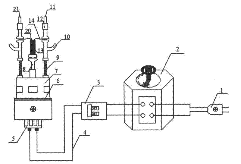
[0045] A new type of ignition temperature measuring device for experiments, comprising an ignition wire 14, an ignition power supply 5, and an ignition platform 7. The ignition platform 7 made of high-voltage and high-temperature-resistant stainless steel is provided with a first point of polytetrafluoroethylene insulating material Fire hole 15 and the second ignition hole 22; Ignition temperature measuring cylinder 13 is placed on the support 8 above the central part of the ignition platform 7; Ignition wire 14 is placed above the ignition temperature measuring cylinder 13; bracket 10, clip spring 9, tight The first ignition column 11 and the second ignition column 21 of the fixed rotary piece 12 are fixed on the ignition platform 7, and are respectively connected with the ignition power supply 5 through the first ignition hole 15 and the second ignition hole 22 of the ignition platform 7; 5 is to be connected by wire 4 by plug 1, power-off protector 3, contact voltage regulat...

Embodiment 2

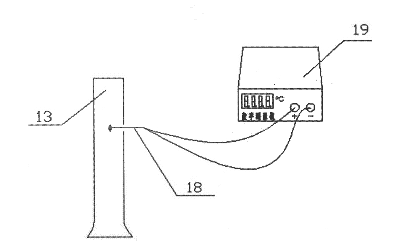
[0048] A new type of ignition temperature measuring device for experiments, comprising an ignition wire 14, an ignition power supply 5, and an ignition platform 7. The ignition platform 7 made of high-voltage and high-temperature-resistant stainless steel is provided with a first point of polytetrafluoroethylene insulating material Fire hole 15 , second ignition hole 22 , first temperature measurement hole 16 and second temperature measurement hole 23 . Ignition and temperature measuring tube 13 is placed on the bracket 8 above the center of the ignition platform 7; ignition wire 14 is placed above the ignition and temperature measuring tube 13; The second ignition column 21 is fixed on the ignition platform 7, and is connected with the ignition power supply 5 by the first ignition hole 15 and the second ignition hole 22 of the ignition platform 7 respectively; , The contact voltage regulator 2 is connected through a wire 4 . There is a small hole on the ignition temperature ...

Embodiment 3

[0051] A new type of ignition temperature measuring device for experiments, comprising an ignition wire 14, an ignition power supply 5, and an ignition platform 7. The ignition platform 7 made of high-voltage and high-temperature-resistant stainless steel is provided with a first point of polytetrafluoroethylene insulating material Fire hole 15 , second ignition hole 22 , first temperature measurement hole 16 and second temperature measurement hole 23 . Ignition and temperature measuring tube 13 is placed on the bracket 8 above the center of the ignition platform 7; ignition wire 14 is placed above the ignition and temperature measuring tube 13; The second ignition column 21 is fixed on the ignition platform 7, and is connected with the ignition power supply 5 by the first ignition hole 15 and the second ignition hole 22 of the ignition platform 7 respectively; , The contact voltage regulator 2 is connected through a wire 4 . There is a small hole on the ignition temperature ...


PUM


Abstract

The invention discloses a novel ignition temperature measuring device for experiment, aiming at providing an ignition device which ignites fuel only by using heat generated by an ignition wire. The device disclosed by the invention comprises an ignition wire, an ignition power source and an ignition platform. A first ignition hole, a second ignition hole, a first temperature measuring hole and a second temperature measuring hole are arranged on the ignition platform. An ignition temperature measuring cylinder is arranged on a bracket above the center of the ignition platform and is provided with a small hole and a thermocouple, and the thermocouple is connected with a thermometer through the first temperature measuring hole and the second temperature measuring hole on the ignition platform via a lead wire. The ignition wire is arranged above the ignition temperature measuring cylinder, two ends of the ignition wire are fixed at a first ignition column and a second ignition column which are externally sleeved with a bracket, a pressure spring and a fastening rotary sheet respectively. The first ignition column and the second ignition column are fixed on the ignition platform and are connected with the ignition power source respectively through the first ignition hole and the second ignition hole on the ignition platform, and the ignition power source is formed in such a manner that a plug, a power-off protector and a contact type voltage regulator are connected via the lead wire. The device disclosed by the invention is mainly used for fuel ignition and temperature measurement during fuel combustion in a laboratory.

Description

technical field [0001] The invention relates to an ignition device, more specifically, relates to an ignition device for experiments that does not require ignition powder to ignite. Background technique [0002] The ignition process of high-energy fuels (such as aluminum / water-based fuels) is of great importance for many combustion and propulsion applications and for revealing the combustion mechanism of high-energy fuels. At present, the ignition methods used in the research on the combustion of high-energy fuels include: chemical ignition, gunpowder ignition, laser ignition and electric ignition. Using chemical ignition, the device is relatively complicated and there are many components, which is not conducive to simplifying the system and improving reliability. The use of igniter needs to select the appropriate ratio according to the combustion characteristics of the fuel. The ignition of gunpowder is to ignite the gunpowder through the resistance wire. The ignition pow...

Claims


Application Information

Patent Timeline
Patent Type & Authority Applications(China)
IPC IPC(8): F23Q7/00G01K7/02
Inventor 孙运兰朱宝忠匡政孙华建李朝祥
Owner ANHUI UNIVERSITY OF TECHNOLOGY
Learn More