
Accurate positioning and detecting method and device for damages of underground metal pipeline anticorrosive coating

A metal pipeline, precise positioning technology, applied in pipeline systems, mechanical equipment, gas/liquid distribution and storage, etc., can solve the problem of not being able to accurately obtain the damaged position, and achieve the effect of simple structure, high positioning accuracy and low cost.

Active Publication Date: 2011-11-23
HUADIAN ENERGY COMPANY LIMITED
View PDF4 Cites 27 Cited by
  • Summary
  • Abstract
  • Description
  • Claims
  • Application Information

AI Technical Summary

Problems solved by technology

The commonly used standard pipe-to-ground potential (P / S) test method usually only obtains data at predetermined measuring points, and cannot accurately obtain the damage location

Method used


Image

  • Accurate positioning and detecting method and device for damages of underground metal pipeline anticorrosive coating
  • Accurate positioning and detecting method and device for damages of underground metal pipeline anticorrosive coating
  • Accurate positioning and detecting method and device for damages of underground metal pipeline anticorrosive coating

Examples


Embodiment 1

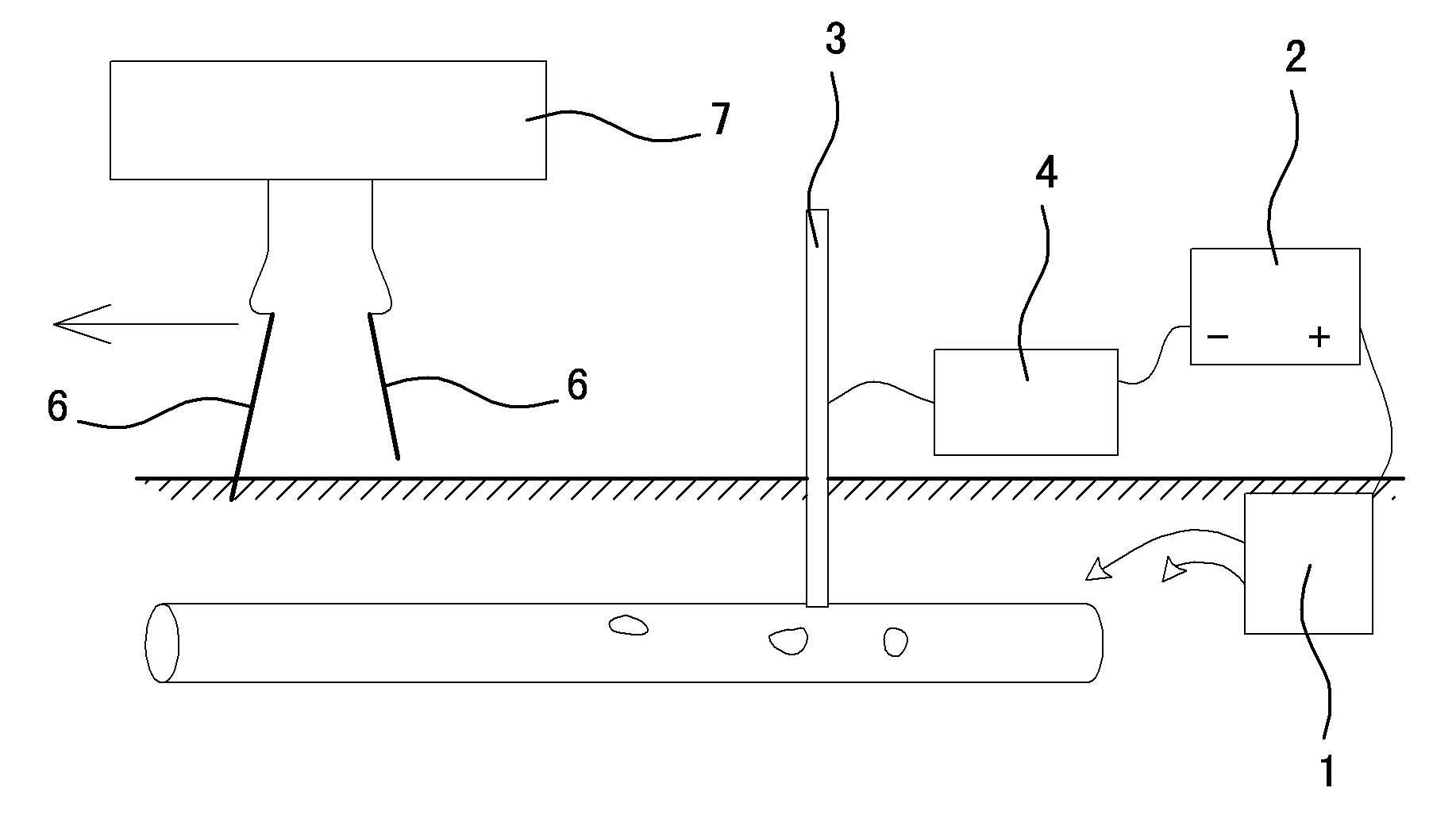
[0027] Embodiment one, such as figure 1 As shown, it includes an excitation signal device and a signal detection device. For a buried pipeline with a cathodic protection system, the excitation signal device is composed of a grounded anode 1, a cathodic protection rectifier 2, a buried pipeline test pile 3 and a current interrupter 4. The grounded anode 1, which is connected to the ground underground, is connected to the positive pole of the cathodic protection rectifier 2 through a wire, and inserted into the ground. The buried pipeline test pile 3 connected to the buried metal pipeline is connected to one end of the current interrupter 4 through a wire, and the current is interrupted. The other end of the device 4 is connected to the negative pole of the cathodic protection rectifier 2, and the buried pipeline test pile 3, the current interrupter 4, the cathodic protection rectifier 2 and the grounding anode 1 are connected in sequence to form an excitation signal circuit; th...

Embodiment 2

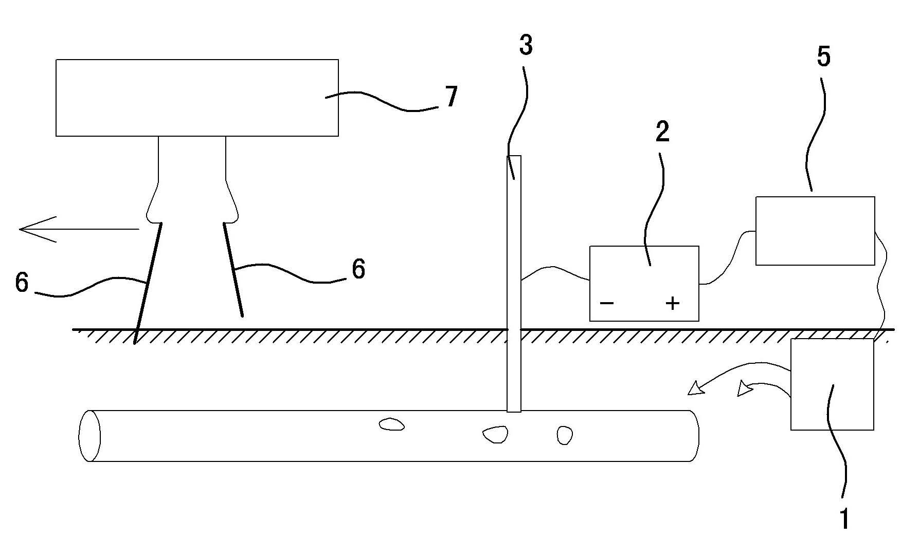
[0030] Embodiment two, such as figure 2 As shown, the difference from Embodiment 1 is that for a buried pipeline without a cathodic protection system, the excitation signal device is composed of a grounded anode 1, an external constant current source 5, a buried pipeline test pile 3 and a current interrupter 4. The positive pole of the external constant current source 5 is connected to one end of the current interrupter 4 through a wire, and the other end of the current interrupter 4 is connected to the grounding anode 1 buried underground and connected to the earth through a wire, and inserted into the ground to connect with the buried metal pipeline The buried pipeline test pile 3 is connected to the negative pole of the external constant current source 5 through wires, and the buried pipeline test pile 3, the external constant current source 5, the current interrupter 4 and the grounding anode 1 are connected in sequence to form an excitation signal circuit.

[0031] The p...


PUM


Abstract

The invention relates to an accurate positioning and detecting method and device for damages of an underground metal pipeline anticorrosive coating. The method comprises the following steps: a current interrupter periodically turns on or off a constant current source through the constant current source, and provides excitation signals for an underground pipeline; the ground voltages of two points along the underground pipeline route are measured by utilizing two saturation copper sulfate reference electrode detection canes which are connected with a signal measurement processor respectively; the signal measurement processor measures, records and displays the turn-on and turn-off of the pipe ground voltages; and the position of the damaged part of the underground pipeline can be determined according to the pipe ground turn-on and turn-off voltages. Through the method, the position of the damage point of the anticorrosive coating can be confirmed accurately, the detection accuracy of the damage for the underground pipeline anticorrosive coating is improved, and important guarantee is provided for mastering the normal operation situation of the pipeline, ensuring the safe operation of the pipeline and the convenience for pipeline maintenance and management.

Description

technical field [0001] The invention relates to a method and a device for accurately locating and detecting damage to an anticorrosion layer of an underground metal pipeline. Background technique [0002] Buried metal pipelines transport various media and have high working pressure, and the environment changes greatly along the way. At present, most of them adopt the outer anti-corrosion layer for pipeline anti-corrosion. Affected by various factors, the anti-corrosion layer will be aging and damaged. How to determine the aging of the anti-corrosion layer, The location of damage and water seepage and timely repair are one of the necessary conditions to reduce the risk of pipeline corrosion and ensure the safe operation of buried metal pipelines. [0003] At present, the operation and management of buried metal pipelines mostly use the observation of changes in flow and pressure values ​​to judge whether the pipeline is damaged or leaked, which fails to prevent pipeline damag...

Claims


Application Information

Patent Timeline
IPC IPC(8): F17D5/02
Inventor 柏春光
Owner HUADIAN ENERGY COMPANY LIMITED
Learn More