
Capsule array type mobile rescue capsule structure

A kind of rescue cabin, cabin type technology, applied in safety devices, mining equipment, earthwork drilling and other directions, can solve the problems of inability to use independently, hidden dangers, time-consuming and laborious, etc., to achieve convenient combination, enhance impact resistance and sealing performance , flexible effect

Active Publication Date: 2011-11-23
武越
View PDF6 Cites 6 Cited by
  • Summary
  • Abstract
  • Description
  • Claims
  • Application Information

AI Technical Summary

Problems solved by technology

Each cabin unit is only a part and cannot be used independently. It can only be put into use after the secondary assembly in the mine is completed.
Due to the limitation of the underground site conditions, the secondary assembly work is more difficult and time-consuming, and the quality of the mobile rescue cabin after the secondary assembly, especially the sealing performance, is not easy to guarantee
In addition, under the existing technical conditions, there is no effective test method for the performance of the assembled mobile rescue cabin, so there is a big hidden danger in the use of this split assembled mobile rescue cabin
[0005] It can be seen that the above-mentioned existing mobile rescue cabin obviously still has inconvenience and defects in structure and use, and needs to be further improved urgently.
In order to solve the above-mentioned problems, the relevant manufacturers have tried their best to find a solution, but no suitable design has been developed for a long time, and the general products do not have a suitable structure to solve the above-mentioned problems. This is obviously related. The problem that the industry is eager to solve

Method used


Image

  • Capsule array type mobile rescue capsule structure
  • Capsule array type mobile rescue capsule structure
  • Capsule array type mobile rescue capsule structure

Examples


Embodiment Construction

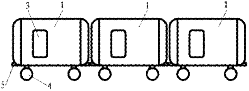
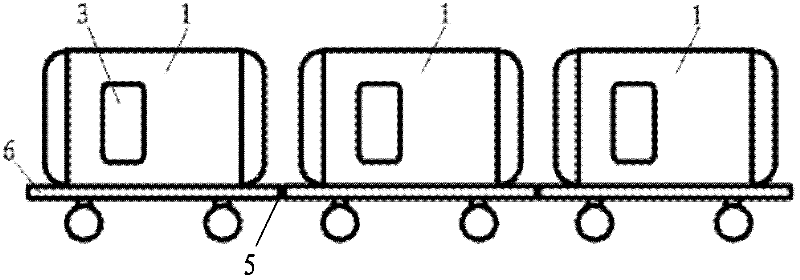
[0026] For further elaborating the technical means and effects that the present invention takes to reach the intended invention purpose, below in conjunction with accompanying drawing and preferred embodiment, to its concrete implementation, structure, characteristic of the cabin column type mobile rescue cabin structure that proposes according to the present invention And its effect, detailed description is as follows.

[0027] The aforementioned and other technical contents, features and effects of the present invention will be clearly presented in the following detailed description of preferred embodiments with reference to the drawings. Through the description of the specific implementation mode, when the technical means and functions adopted by the present invention to achieve the predetermined purpose can be obtained a deeper and more specific understanding, but the accompanying drawings are only for reference and description, and are not used to explain the present inven...


PUM


Abstract

The invention relates to a capsule array type mobile rescue capsule structure. A mobile rescue capsule of specified population is partitioned into a plurality of independent mobile rescue capsule units, and the independent mobile rescue capsule units are combined into a capsule array through traction connecting mechanisms or a flat transport vehicle. Each mobile rescue capsule unit is an integral working unit, and comprises a capsule body structure, a sealed door, a wheel axle mechanism, a wheel, a traction connecting mechanism and internal equipment; a transition capsule is arranged or not arranged in each mobile rescue capsule unit; and the overall dimension and the weight of each mobile rescue capsule unit are in a transport allowed range of different mines. The mobile rescue capsule is split into the plurality of mobile rescue capsule units with small volume and light weight, and the mobile rescue capsule units are transported to the mine from the ground through a limited cage space respectively and connected into the capsule array in the mine, so that quick underground movement, placement and installation are realized, the sealing performance of the capsule body can be ensured, and the impact resistance of the capsule body can be improved.

Description

technical field [0001] The invention relates to the technical field of mine safety, in particular to a cabin-type mobile rescue cabin structure that provides safe refuge for people who cannot evacuate when an underground catastrophe occurs in a mine. Background technique [0002] The mobile rescue cabin is an important part of the emergency avoidance system of mines and related industries. It is used to provide life support equipment for people in distress underground when an emergency occurs at the production site of mines and related industries. The mobile rescue cabin is a kind of safe-haven facility that can be moved by traction, hoisting, etc. to adapt to the changing requirements of the work site. [0003] When a disaster accident occurs at the production site of mines and related industries, the mobile rescue cabin can provide a confined space for life support for those in distress who cannot evacuate in time. Therefore, the mobile rescue cabin can resist high-temper...

Claims


Application Information

Patent Timeline
Patent Type & Authority Applications(China)
IPC IPC(8): E21F11/00
Inventor 武越
Owner 武越
Learn More