Electromagnetic weft insertion weft carrier, rapier for electromagnetic weft insertion as well as electromagnetic weft insertion method

A weft carrier and weft insertion technology, applied in the field of electromagnetic weft insertion weft carrier, rapier for electromagnetic weft insertion and electromagnetic weft insertion, can solve the problems of reducing the service life of shuttles, flying off the shed, reducing the success rate of weft insertion and Weaving efficiency and other issues to achieve the effect of increased life, easy operation, simple structure

Inactive Publication Date: 2011-11-23
JINGWEI TEXTILE MASCH CO LTD
View PDF7 Cites 5 Cited by
  • Summary
  • Abstract
  • Description
  • Claims
  • Application Information

AI Technical Summary

Problems solved by technology

[0002] The weft insertion method of the currently used shuttle loom is to set a shed on the loom, and hit the shuttle (weft carrier) to make it slide back and forth in the shed. In this weft insertion method, the shuttle is in free flight during movement. State, so the shuttle has a phenomenon of flying off the shed, which reduces the success rate of weft insertion and weaving efficiency. At the same time, repeatedly hitting the shuttle will also reduce the service life of the shuttle.

Method used


Image

  • Electromagnetic weft insertion weft carrier, rapier for electromagnetic weft insertion as well as electromagnetic weft insertion method
  • Electromagnetic weft insertion weft carrier, rapier for electromagnetic weft insertion as well as electromagnetic weft insertion method
  • Electromagnetic weft insertion weft carrier, rapier for electromagnetic weft insertion as well as electromagnetic weft insertion method

Examples


Embodiment Construction

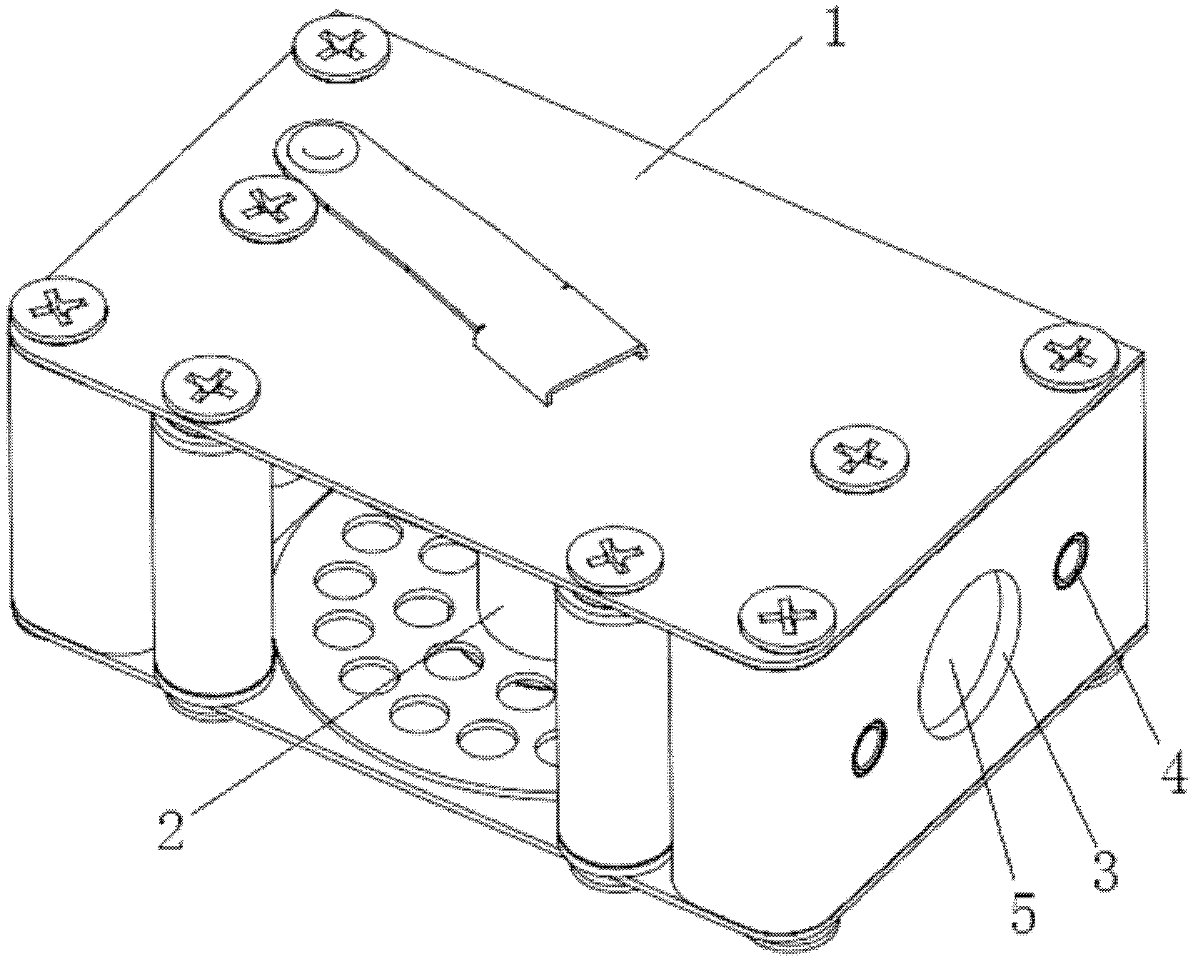
[0025] Such as figure 1 As shown, it is the electromagnetic weft insertion carrier of the present invention, which includes a shuttle box 1 and a yarn storage device 2 located in the shuttle box 1, and the corresponding two side walls of the shuttle box 1 are respectively provided with a wire for electromagnetic weft insertion. permanent magnet 5 and two positioning holes 4. The inner wall of the positioning hole 4 is provided with a copper sleeve for preventing the positioning hole from being worn and affecting the positioning effect. The cross section of the positioning hole 4 is circular. Two corresponding side walls of the shuttle box 1 are respectively provided with an inward counterbore 3 , and a permanent magnet 5 is fixed in the counterbore 3 . The top surface of the permanent magnet 5 is lower than the outer surface of the side wall of the shuttle box 1 . When the section of positioning hole 4 is circular, two positioning holes need to be set, and the weft carrier i...


PUM


Abstract

The invention provides an electromagnetic weft insertion weft carrier with high efficiency of weft inserting and weaving, an electromagnetic weft insertion device and an electromagnetic weft insertion method. The electromagnetic weft insertion weft carrier provided by the invention comprises a shuttle box and a yarn storage device arranged in the shuttle box, wherein two corresponding side walls of the shuttle box are respectively provided with a permanent magnet used for electromagnetic weft insertion and at least one locating hole. According to the electromagnetic weft insertion weft carrier, a rapier for the electromagnetic weft insertion, and the electromagnetic weft insertion method provided by the invention, no an additional shuttle path is needed, the weft carrier is moved in the air by using an electromagnetic action and always in a controlled state so that the weft carrier is prevented from being hit, free flight of the weft carrier is prevented, and the service life of the weft carrier, success rate of weft insertion and weaving efficiency are all increased; in addition, the weft insertion device has the advantages of simple structure and convenience for operation.

Description

technical field [0001] The invention relates to a loom weft carrier, a weft insertion device and a weft insertion method, in particular to an electromagnetic weft insertion weft carrier, a rapier for electromagnetic weft insertion and an electromagnetic weft insertion method. Background technique [0002] The weft insertion method of the currently used shuttle loom is to set a shed on the loom, and hit the shuttle (weft carrier) to make it slide back and forth in the shed. In this weft insertion method, the shuttle is in free flight during movement. state, so the shuttle has a phenomenon of flying away from the shed, which reduces the success rate of weft insertion and the efficiency of weaving. At the same time, repeatedly hitting the shuttle will also reduce the service life of the shuttle. [0003] In addition, the patent No. ZL9510658.5, which is called the weft insertion method and device of the rapier loom, discloses a method of using electromagnetic force to open the ...

Claims


Application Information

Patent Timeline
Patent Type & Authority Applications(China)
IPC IPC(8): D03D47/18D03D47/20D03D49/44
Inventor 袁树信李伟张卫东宋智燕余文斌马小丽
Owner JINGWEI TEXTILE MASCH CO LTD
Why Eureka
Try Eureka