
High-dryness filter and method

A high-dryness, filter technology, applied in the direction of filtration separation, separation methods, chemical instruments and methods, etc., can solve the problems of high labor intensity, difficulty in separating the filter cake from the filter cloth, explosive frame, etc., to save labor costs, Low energy consumption and the effect of increasing solid content

Inactive Publication Date: 2011-11-23
扬州永泰环保科技有限公司 +2
View PDF4 Cites 17 Cited by
  • Summary
  • Abstract
  • Description
  • Claims
  • Application Information

AI Technical Summary

Problems solved by technology

Existing filter presses are mainly divided into traditional plate-and-frame (or box-type) and belt-type. The plate-and-frame filter press requires manual operation, which is labor-intensive, cannot withstand high pressure, and is easy to burst
The belt filter press uses the pressure between the filter belt and the roller or the pressure belt to filter the solid-liquid mixture on the filter belt. Although the filtration is continuous, the filter pressure cannot be too high because both sides of the filter belt are open. To prevent the material to be filtered from being extruded from both sides of the filter belt, so the solid-liquid separation after filtration is not ideal
After the separation of the above two equipments, the water content is as high as 80%. This kind of sludge needs to be reprocessed. The treatment cost is very high, and the sludge pollutes the environment and cannot be disposed of. The filter cake after filtration is difficult to separate from the filter cloth

Method used


Image

  • High-dryness filter and method
  • High-dryness filter and method
  • High-dryness filter and method

Examples


Embodiment Construction

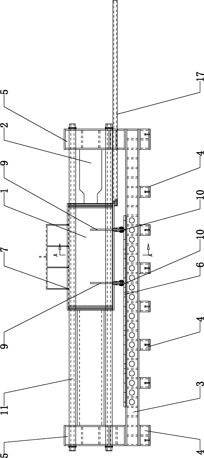
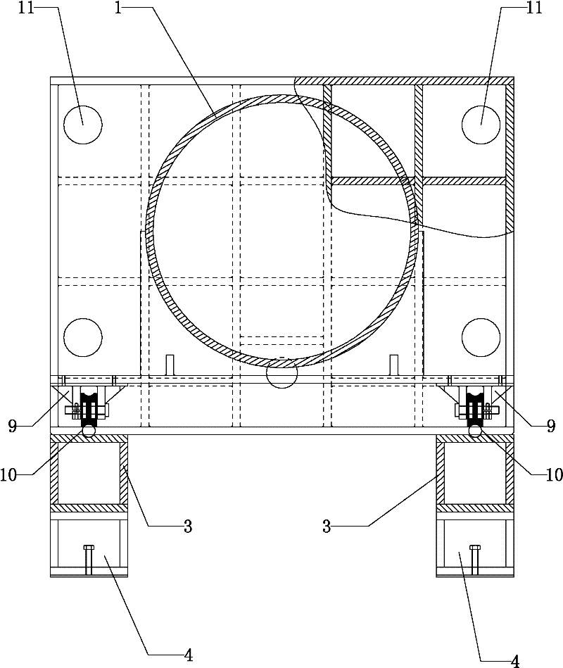
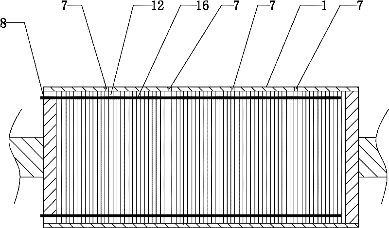
[0026] Such as Figure 1-6 As shown, one form of the present invention described in the embodiment of the present invention is a high-dryness filter, including a cylinder body 1, a hydraulic cylinder 2 and two beam joints 3, and the two beam joints 3 The bottom is welded with a number of foot box joints 4 respectively, and the tops of the two beam joints 3 are provided with side box joints 5 near both ends, and the bottoms of the side box joints 5 are welded to the two cross beam joints 3 respectively. On the top, two crossbeam joints 3 are provided with guide rails 6 close to the middle, and a cylinder body 1 is arranged above the guide rails 6. Several water inlets 7 are arranged on the outer surface of the cylinder body 1, and the water inlets 7 are connected to the water inlet pipes. The left end face of the body 1 is provided with a water outlet 8, the bottom of the cylinder body 1 is provided with a supporting rod 17 near the right end, and the front and rear sides of th...


PUM


Abstract

The invention relates to a high-dryness filter and a method. The high-dryness filter comprises a cylinder body, a hydraulic cylinder and two crossbeam binders, wherein a plurality of foot box binders are welded on the bottoms of the two crossbeam binders respectively; lateral box binders are arranged at the positions, which are close to both ends, on the tops of the two crossbeam binders; the bottoms of the lateral box binders are welded on the two crossbeam binders respectively; guide rails are arranged at the positions, which are close to middle parts, on the two crossbeam binders; the cylinder body is arranged above the guide rails; the front and rear sides of the cylinder body are provided with a plurality of cylinder body support binders respectively; the bottoms of the cylinder body support binders are arranged on the guide rails through wheels; a fixed piston on the left side of the cylinder body is connected with the lateral box binder on the left side through welding; and a movable piston on the right side of the cylinder body is connected with a hydraulic rod of the hydraulic cylinder. The high-dryness filter has the advantages that: the solid content of mud cakes is improved, the automation degree is extremely high, and the energy consumption is extremely low; and the moisture content of the mud cakes is low, the mud cakes are convenient to transport and treat, and the aim of drying, and the aims of emission reduction and innocent treatment are also fulfilled.

Description

technical field [0001] The invention relates to a high dryness filter and a method. Background technique [0002] The main function of the filter press is to separate the solid-liquid mixture. Existing filter presses are mainly divided into traditional plate-and-frame (or box-type) and belt-type. The plate-and-frame filter press requires manual operation, which is labor-intensive, cannot withstand high pressure, and is easy to burst the frame. The belt filter press uses the pressure between the filter belt and the roller or the pressure belt to filter the solid-liquid mixture on the filter belt. Although the filtration is continuous, the filter pressure cannot be too high because both sides of the filter belt are open. In order to prevent the material to be filtered from being extruded from both sides of the filter belt, the solid-liquid separation after filtration is not ideal. After the separation of the above two equipments, the water content is as high as 80%. This kin...

Claims


Application Information

Patent Timeline
IPC IPC(8): B01D25/12B01D37/00
Inventor 朱德海陈莉莉
Owner 扬州永泰环保科技有限公司
Learn More