
Display panel module and display device

A display screen, staggered configuration technology, applied in the direction of identification devices, printed circuits, electrical equipment structural parts, etc., can solve problems such as increased power consumption, increased heating temperature, and reduced display quality, and achieves the effect of improving heat dissipation characteristics

Inactive Publication Date: 2011-11-16
PANASONIC CORP
View PDF1 Cites 9 Cited by
  • Summary
  • Abstract
  • Description
  • Claims
  • Application Information

AI Technical Summary

Problems solved by technology

Here, the larger the display screen of a TV or the like, or the larger the number of pixels, the more obvious the above-mentioned problems. Therefore, according to the conventional structure, it is difficult to reduce the number of drive circuit elements.
[0009] Moreover, another problem when reducing the number of drive circuit elements 6 is that if the number of drive circuit elements 6 is reduced, the number of outputs per drive circuit element 6 will increase.
That is, the circuit scale of each driving circuit element 6 increases, and the power consumption increases
As a result, the heating temperature of the driving circuit element 6 itself rises, exceeding the guaranteed temperature of the driving circuit element 6, or deteriorating the characteristics of the driving circuit element 6, resulting in a decrease in display quality.

Method used


Image

  • Display panel module and display device
  • Display panel module and display device
  • Display panel module and display device

Examples


Embodiment 1

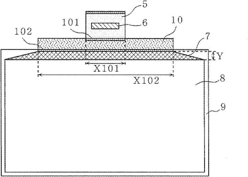
[0075] figure 1 is a plan view showing the structure of the display panel module in this embodiment.

[0076] The display module includes a film package 5 , a display 9 and a flexible printed board 10 . This display module has a structure in which the electrodes (terminals) of the film package 5 are connected to the display panel through the flexible printed board 10 while reducing the number of drive circuit elements 6 mounted on the film package 5 to one. 9 electrodes (terminals) are connected. Here, by making the width X102 of the connecting portion 102 between the flexible printed board 10 and the display screen 9 longer than the width X101 of the connecting portion 101 between the thin film package 5 and the flexible printed board 10, it is compatible with the thin film package 5 and the flexible printed board 10. Compared with the case where the display screen 9 is directly bonded, the length Y in the vertical direction of the wiring region 7 located on the display sc...

Deformed example 1

[0084] Second, use Figure 4 A modified example of the display module according to this embodiment will be described.

[0085] Such as Figure 4 It shows that in the display module of this modified example, by making the shape of the flexible printed board 10 trapezoidal, the area of ​​the flexible printed board 10 can be suppressed to a necessary and minimum limit, and the number of parts required for the display module can be reduced. the cost of.

[0086] A plurality of electrodes 301 connected to the film package 5 are arranged on the upper bottom of the trapezoidal-shaped flexible printed board 10, and a plurality of electrodes 302 connected to the display screen 9 are arranged on the trapezoidal-shaped flexible printed board 10. The bottom of the plate 10. Also, the lower base of the trapezoidal shape is a side longer than the upper base.

Deformed example 2

[0088] Second, use Figure 5 Another modified example of the display module according to the present embodiment will be described.

[0089] Such as Figure 5 As shown, the display module of this modified example has a structure in which a circuit element (hereinafter referred to as a control circuit element) 1 and a driving circuit element 6 are mounted on one thin film package 5, that is, a plurality of circuit elements are mounted on one thin film package 5. , a control circuit for controlling the drive circuit of the display screen 9 is mounted (mounted) on the circuit element (hereinafter, control circuit element) 1 . According to the structure of the present embodiment, in the display panel module, the number of drive circuit elements 6 can be reduced to one. As a result, by reducing the Figure 17 In the structure of the conventional display module shown, the cable 3, the source substrate 4, and the control substrate 2 used to connect the control circuit element 1 to a...


PUM


Abstract

Disclosed is a display panel module capable of increasing heat releasing performance of a driving circuit element and capable of reducing the number of display circuit elements without reducing the number of display panels produced from the display panel module. Specifically disclosed is a display panel module which comprises a film package (5), a display panel (9), and a flexible printed circuit board (10). The flexible printed circuit board (10) has a plurality of electrodes (301) connected to the film package (5), and a plurality of electrodes (302) that are disposed with a pitch larger than that of the electrodes (301) and that are connected to the display panel (9), and the flexible printed circuit board (10) that relays pixel data between the film package (5) and the display panel (9).

Description

technical field [0001] The present invention relates to a display module, and more particularly, to a display module aimed at reducing the number of circuit elements (hereinafter, driving circuit elements) mounted with a driving circuit for a display such as a liquid crystal panel and reducing the cost of the display module. Background technique [0002] In recent years, the market for flat panel display devices such as liquid crystal panels, plasma panels, and organic electroluminescence panels, which are display devices such as televisions and monitors, has gradually expanded. And, along with the expansion of the market, the price reduction of flat panel display devices has been accelerated. As a result, the market for flat panel display devices is further expanding, and cost reduction of display modules and peripheral devices is an essential condition for the manufacture of flat panel display devices. [0003] here, Figure 17 A plan view showing a general structure of a...

Claims


Application Information

Patent Timeline
Patent Type & Authority Applications(China)
IPC IPC(8): G09F9/00G02F1/1345H05K1/02H05K1/14H05K7/20
CPCH05K1/147H05K7/20963H05K1/117H05K2201/10128G02F1/13452H05K2201/09227
Inventor 北山裕己小川宗彦石川智也小岛宽西和义须山透
Owner PANASONIC CORP
Learn More