Method for determining a state of at least one component of a control unit

A technology for controlling equipment and components, applied in general control systems, program control, control/regulation systems, etc., can solve problems such as device damage, and achieve cost-saving effects

Inactive Publication Date: 2011-11-16
ROBERT BOSCH GMBH
View PDF6 Cites 4 Cited by
  • Summary
  • Abstract
  • Description
  • Claims
  • Application Information

AI Technical Summary

Problems solved by technology

[0002] Electronic devices, such as the control equipment of a car, are subject to wear and tear during operation, which over time can lead to damage to the device, so that it is no longer functional

Method used


Image

  • Method for determining a state of at least one component of a control unit
  • Method for determining a state of at least one component of a control unit
  • Method for determining a state of at least one component of a control unit

Examples


Embodiment Construction

[0029] The invention is schematically illustrated with the aid of an embodiment in the drawing and is explained in more detail below with reference to the drawing.

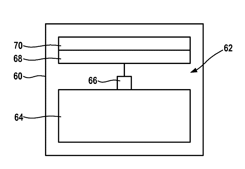
[0030] figure 1 The figure in the figure shows five states, which are transitioned for the control device when carrying out an embodiment of the method: the initialization "INIT" 10 of the control device as the first state, the start "START" 12 of the control device as The second state, the update "UPDATEMAXMINSS" 14 of the minimum value (Min_Temperature) of the temperature (ECU_Temperature) as the third state, the update "UPDATEMAXMINSF" 16 of the maximum value (Max_Temperature) of the temperature (ECU_Temperature) as the fourth state, and the control device The memory (EEPROM) is turned off "ENDEEPROM" 18 as the fifth state. In this figure, the numerical arrows between the states when implementing the method represent transitions 1, 2, 3, 4, 5 between these states, wherein these transitions 1, 2, 3, 4, 5 indica...


PUM


Abstract

The invention relates to a method for determining a state of at least one component of a control unit, wherein a temperature of the at least one component is determined, wherein a type of a temperature change is detected and recorded for a number of temperatures that are determined over a time period, wherein recorded temperature changes are used to determine the state. The invention further relates to an arrangement for determining a state of at least one component of the control unit, a control unit, a computer program, and a computer program product.

Description

technical field [0001] The invention relates to a method for determining the state of a control plant component, a device for determining the state of a control plant component, a control device, a computer program and a computer program product. Background technique [0002] Electronic devices, such as control units of a motor vehicle, are subject to wear and tear during operation, which can lead to damage to the device over time, so that it is no longer functional. In order to identify such damage early, the device usually has to be disassembled and opened so that the components within the device can be inspected. Contents of the invention [0003] The invention relates to a method for determining the state of at least one component of a control device, wherein the temperature of the at least one component is determined or ascertained, wherein a number of temperatures determined or ascertained over a period of time is detected and A manner in which temperature changes a...

Claims


Application Information

Patent Timeline
Patent Type & Authority Applications(China)
IPC IPC(8): G01R31/04
CPCG05B2219/37431G07C3/00
Inventor B.布迪斯卡克T.菲古特T.丁勒M.梅辛格F.普罗哈斯卡
Owner ROBERT BOSCH GMBH
Why Eureka
Try Eureka