
Alcohol receiving station

A connected, highly volatile technology, applied in alcohol receiving equipment and in the field of alcohol receiving, can solve problems such as prolonging the receiving process and disturbing variables, and achieve good degassing, constant mixing accuracy, and good mixing accuracy.

Inactive Publication Date: 2014-12-17
KRONES AG
View PDF6 Cites 0 Cited by
  • Summary
  • Abstract
  • Description
  • Claims
  • Application Information

AI Technical Summary

Problems solved by technology

During the final stages of the tank emptying process, the system is often "stop-and-go" with a low overflow rate, which causes disturbance variables in the subsequent mixing process and prolongs the receiving process. process

Method used


Image

  • Alcohol receiving station
  • Alcohol receiving station
  • Alcohol receiving station

Examples


Embodiment Construction

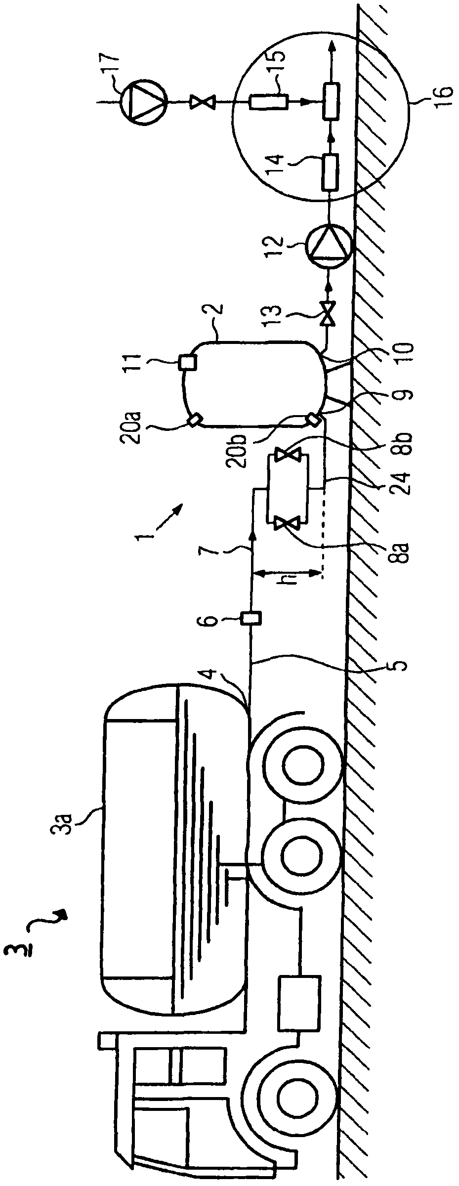
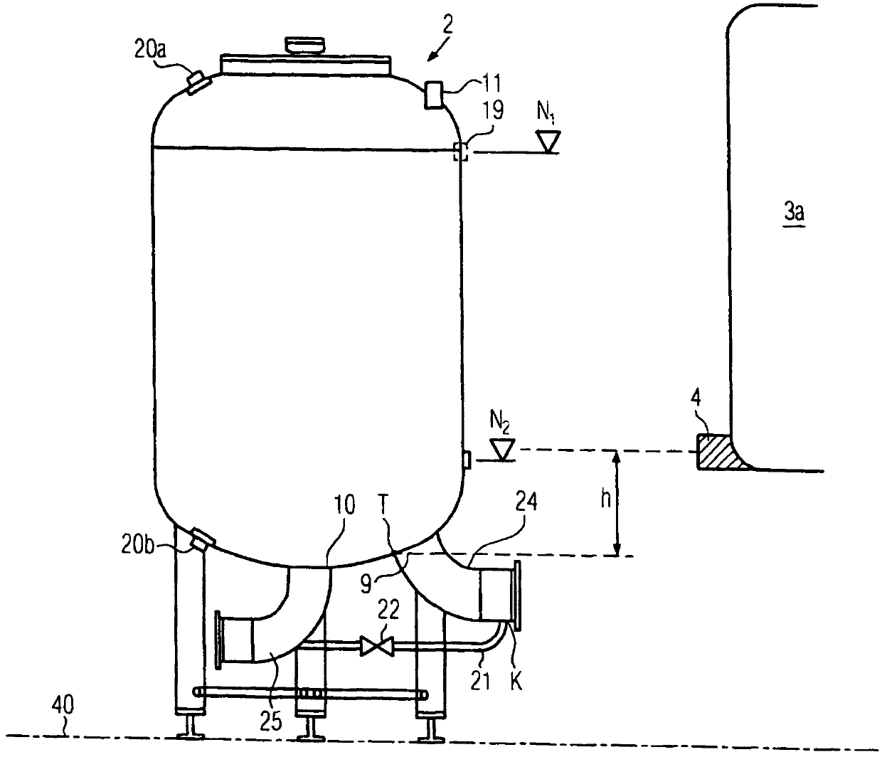
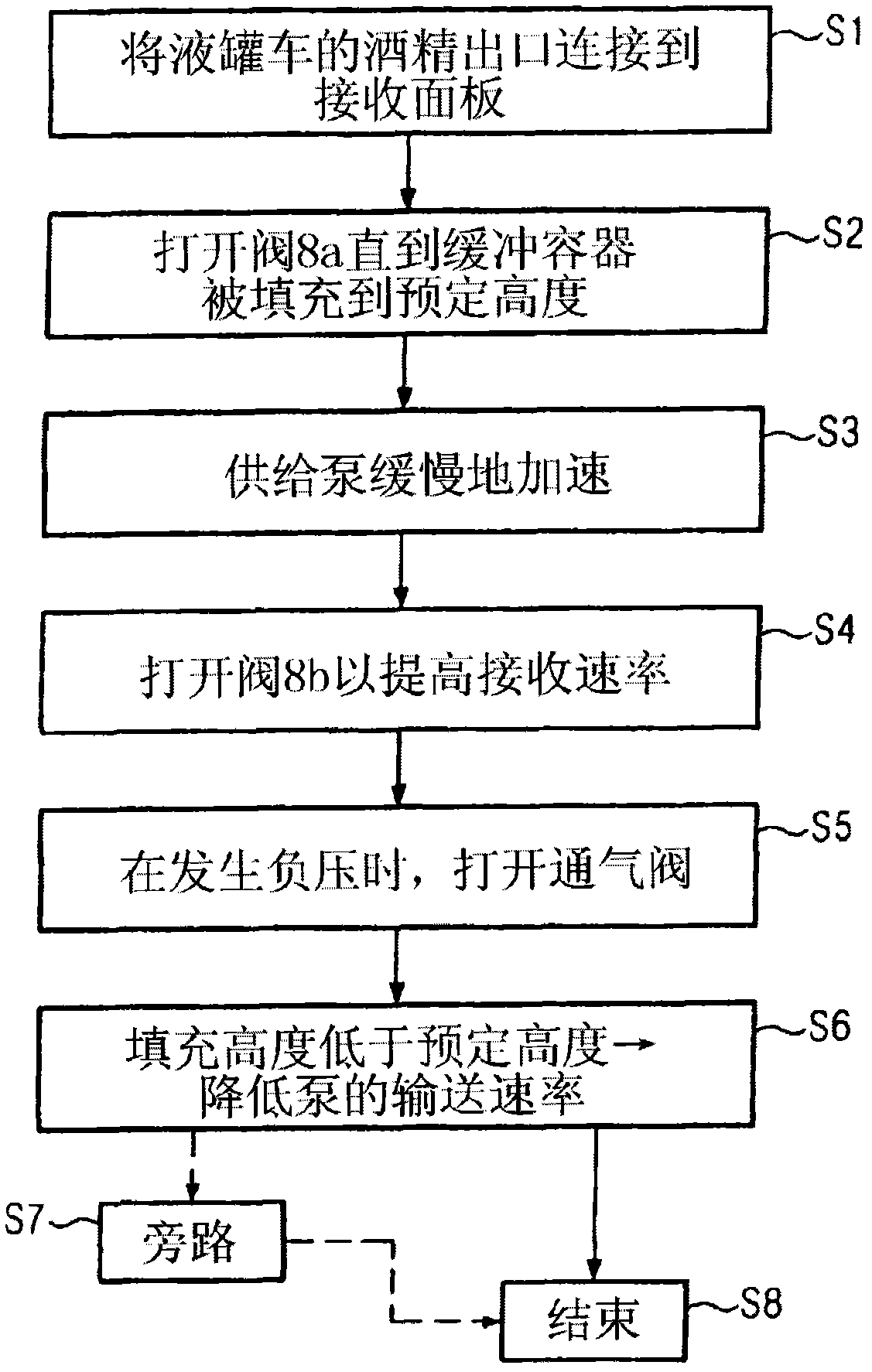
[0028] figure 1 A schematic diagram of a device for receiving alcohol from a tank truck 3 is shown. The tank truck 3 has a liquid tank 3a, the liquid tank 3a has for example a 20 to 40 m 3of storage capacity. In the lower region of the tank 3a there is an alcohol outlet 4, which is connected via a hose 5 and a connection 6 to, for example, a panel 7 of a device for receiving alcohol, which is only schematically depicted as a line in the figure straight line. The panel 7 includes corresponding ducts by means of which alcohol can be introduced into the degassing container 2 . The alcohol supply line is divided into two lines with two valves 8a, 8b arranged parallel to each other. The two lines then flow together again into the common line 8 . The valves 8a, 8b are not regulating valves in which the flow rate can be adjusted, but seat valves with only a low pressure loss. The seat valves 8a, 8b can be opened and closed independently of each other by means of a controller no...


PUM


Abstract

The invention relates to a device and to a method for receiving highly volatile liquids, in particular for receiving alcohol from a tank truck having a degassing container, into which alcohol is conducted from the tank truck, wherein the degassing container has an alcohol inlet and an alcohol outlet. The alcohol inlet and the alcohol outlet are arranged in the lower area of the degassing container, and the device for receiving alcohol may thus be located above ground.

Description

technical field [0001] The present invention relates to an apparatus for receiving highly volatile liquids, in particular alcohol, and to a method for receiving highly volatile liquids, in particular alcohol, said apparatus having a degassing container, highly volatile Liquid, in particular alcohol, is introduced from a tank truck into a degassing container which has an alcohol inlet and an alcohol outlet. Background technique [0002] In order to dilute alcohol, such as ethanol, with water in order to reduce the alcohol from, for example, 96% to below 76%, the alcohol is first received from a tank truck. In the case of using known devices, the alcohol is conveyed from the tank car into a degassing container which serves as a degassing container and is arranged under the base of the tank car. Despite the low acceptance rate, known systems require a fore-running height between the tank truck and the inlet to the degassing vessel of approximately 1.5 to 3 m. The inflow heigh...

Claims


Application Information

Patent Timeline
Patent Type & Authority Patents(China)
IPC IPC(8): B01D19/00B67D7/76
CPCB01D19/0036B01D19/0063B67D7/763
Inventor G·汉克M·索玛
Owner KRONES AG
Learn More