
Semicircular inversed offset scanning for enlarged field of view 3d

A field of view, offset position technology used in the field of C-arm systems

Inactive Publication Date: 2011-11-16
KONINKLIJKE PHILIPS NV
View PDF5 Cites 4 Cited by
  • Summary
  • Abstract
  • Description
  • Claims
  • Application Information

AI Technical Summary

Problems solved by technology

[0007] Therefore, there is room for improvement

Method used


Image

  • Semicircular inversed offset scanning for enlarged field of view 3d
  • Semicircular inversed offset scanning for enlarged field of view 3d
  • Semicircular inversed offset scanning for enlarged field of view 3d

Examples


Embodiment Construction

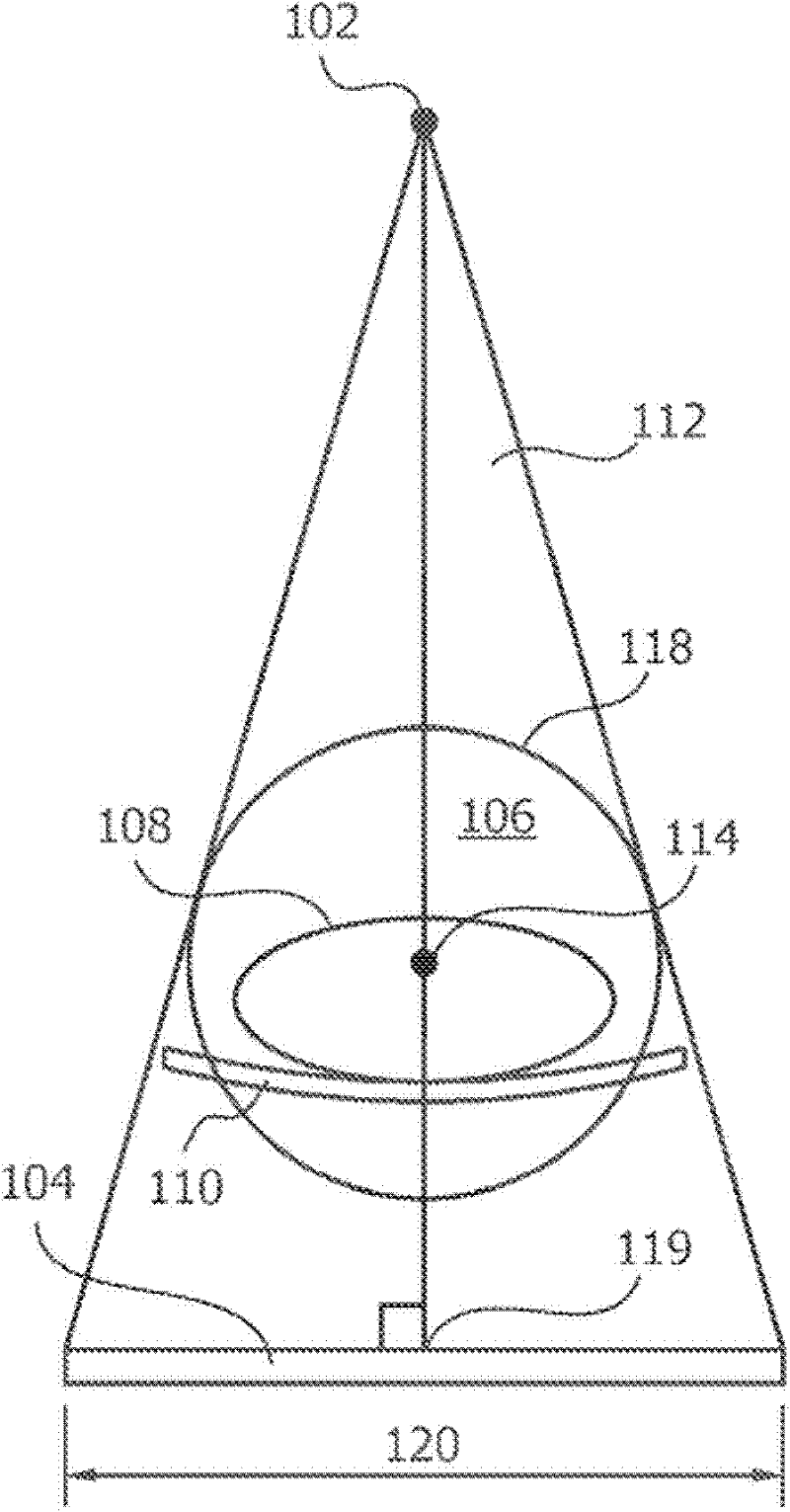
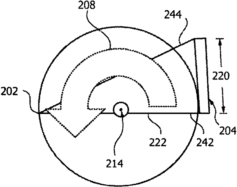
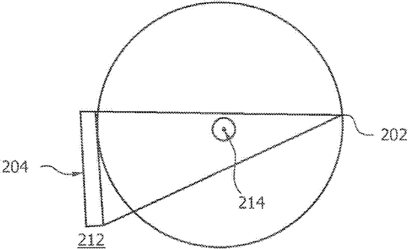
[0043] With respect to the full beam geometry, figure 2 The detector 204 of the imaging system shown in is displaced in a lateral direction by approximately half its lateral dimension or width 120 . A ray or projection 222 with a small distance to the center of rotation 214 is perpendicular to the plane of the detector 204 . At a given projection angle, the detector 204 detects that the Figure 4 Radiation of about half of the FOV 218 shown in (note the overlap or transition region 224 ensures that projection data is acquired in the central region of the lateral FOV 218). Although the half-beam acquisition geometry achieves a relatively large lateral FOV relative to the full-beam geometry shown in the embodiment of FIG. 1 , full angular sampling of the lateral FOV requires data collection over an angular range of approximately 360° . The computed tomography method uses an x-radiation source 202 , on which a detector 204 is mounted on a support (not shown here). A source (2...


PUM


Abstract

A computed tomography acquisition method, an imaging system, a computer readable medium provides laterally displacing a radiation detector (204) from a position with centered detector geometry with a centered transverse field of view to a first offset position (212); emitting first radiation by the radiation source (202), detecting the first radiation by the radiation detector (204) and acquiring projection data indicative of the first radiation; rotating the support around the rotational axis (214) by 180 DEG ; emitting second radiation by the radiation source (202), detecting the second radiation by the radiation detector (204) and acquiring projection data indicative of the second radiation; displacing the radiation detector (204) from the first offset position to a second offset position (226), with opposite direction and double length of the first displacement (a); emitting third radiation by the radiation source (202), detecting the third radiation by the radiation detector (204) and acquiring projection data indicative of the third radiation; rotating the support around the rotational axis (214) by 180 DEG; and emitting fourth radiation by the radiation source (202), detecting the fourth radiation by the radiation detector (204) and acquiring projection data indicative of the fourth radiation.

Description

technical field [0001] The present application relates to methods for use in computed tomography (CT) and X-ray CT equipment. It has particular application in x-ray CT for medical applications. It also has applications in commodity and security inspections, non-destructive testing, preclinical imaging, and other situations where CT data can provide useful information about the structure or function of an object. Furthermore, the present application relates to: an imaging system, such as an X-ray imaging system, precisely a C-arm system; a control device configured to actuate means for displacing a radiation detector; a computer readable medium related to said method and program element. Background technique [0002] One area in which CT imaging systems have gained wide acceptance is medicine, where CT scanners are widely used by radiologists and other medical professionals in connection with the diagnosis and treatment of disease. The relatively recent adoption of multi-s...

Claims


Application Information

Patent Timeline
Patent Type & Authority Applications(China)
IPC IPC(8): A61B6/03
CPCA61B6/4441A61B6/032A61B6/4014A61B6/4435A61B6/4233A61B6/4452A61B6/508
Inventor N·J·努尔德霍尔克
Owner KONINKLIJKE PHILIPS NV
Learn More