Rotor core and method of fastening rotor core and rotary shaft
A technology of rotor iron core and rotating shaft is applied in the field of fastening between the rotor iron core and the rotating shaft, which can solve the problems such as the deformation of the rotor iron core 1, and achieve the effect of reducing the change of magnetic flux and preventing the deformation in the axial direction.
- Summary
- Abstract
- Description
- Claims
- Application Information
AI Technical Summary
Problems solved by technology
Method used
Image

Examples
Embodiment approach 1
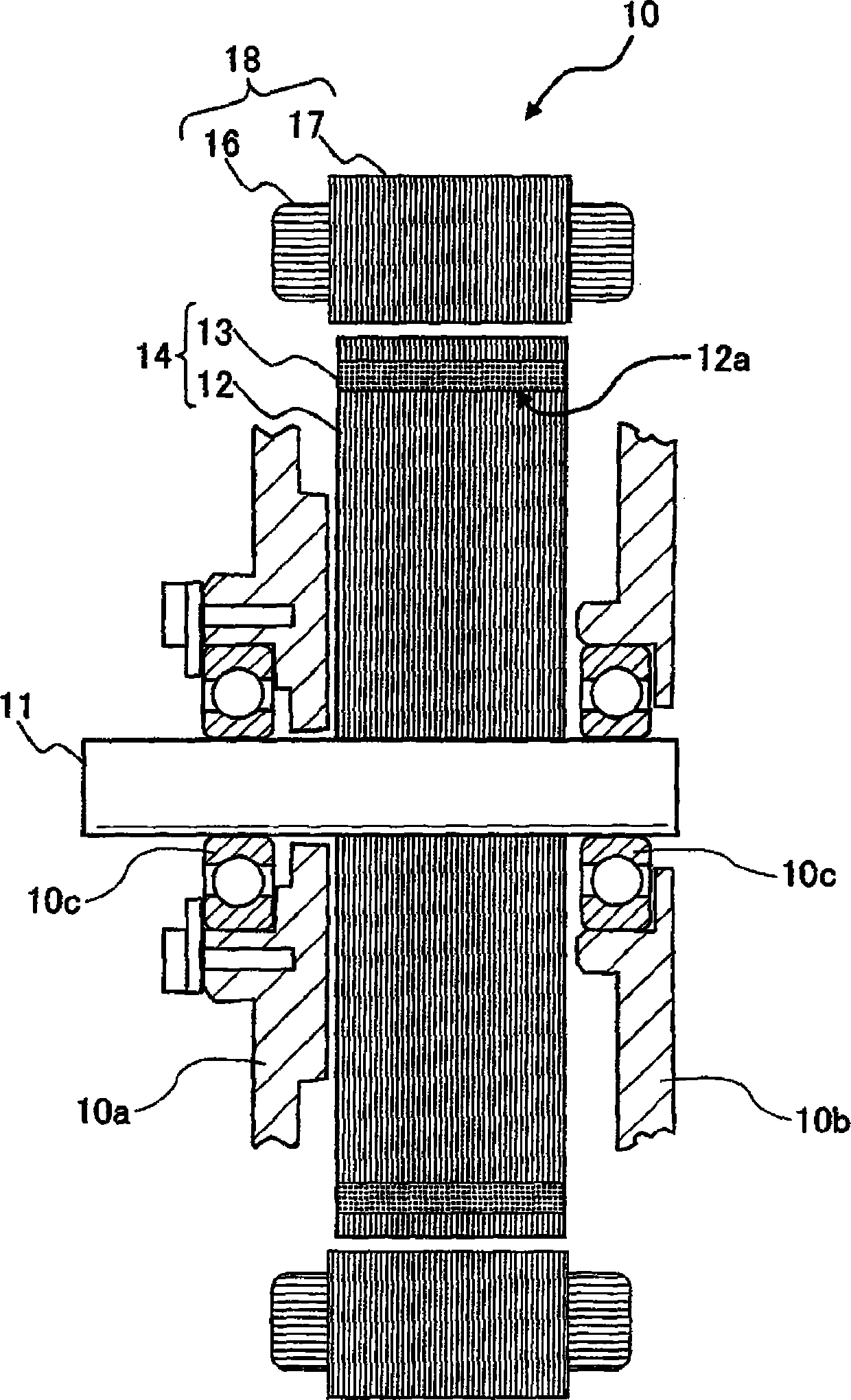
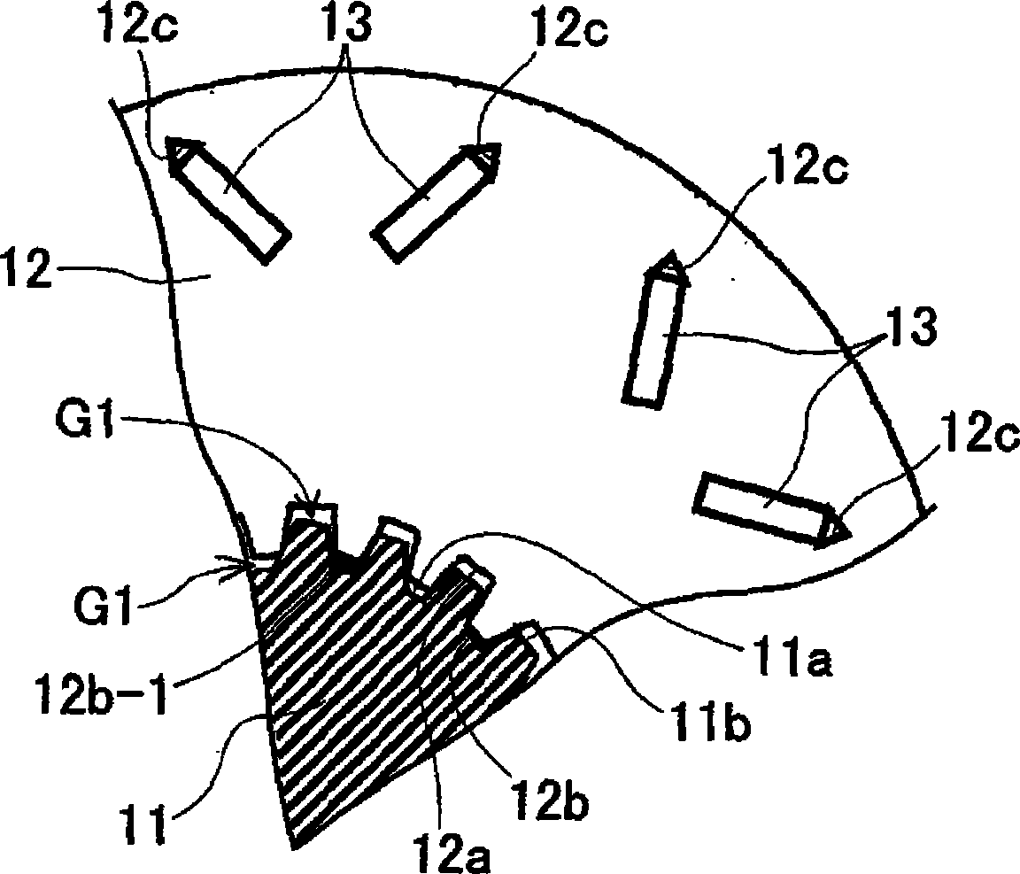
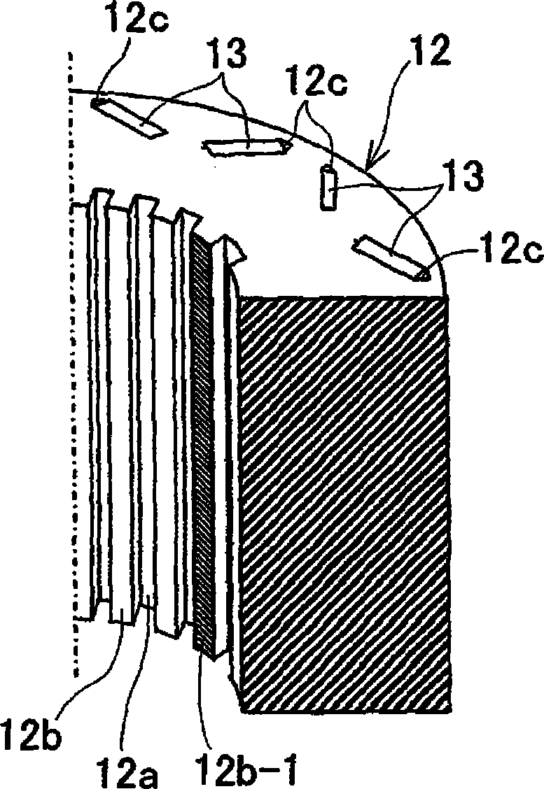
[0074] figure 1 It is an axial sectional view showing the structure of the motor using the rotor core according to the first embodiment. figure 2 It is a partial plan view of the rotor core and a part of the rotating shaft according to Embodiment 1 viewed from the axial direction. image 3 It is a partial perspective view showing main parts of the rotor core according to the first embodiment.
[0075] figure 1 The electric motor (rotating electric machine) 10 shown is, for example, a motor used for mounting on a vehicle such as a hybrid vehicle or an electric vehicle. The electric motor 10 includes a stator 18 having a stator core 17 and a stator coil 16, and Functioning as an armature; rotor 14 having a rotor core 12 and a shaft 11 as a rotating shaft, and functioning as a magnetic field; and a front case 10a and a rear case 10b, the front case 10a and the rear case 10b houses the stator 18 and the rotor 14, and is connected and fixed by fastening bolts (not shown).
...
Deformed example 1
[0093] Figure 8 It is a partial perspective view showing a main part of a rotor core according to Modification 1 of Embodiment 1. FIG. Such as Figure 8 As shown, the welding parts 12b-2, 12b-3 are provided on the protruding end surface of the first protruding bar 12b of the rotor core 12 (or the groove bottom surface of the first groove 12a), and are provided on the protruding end surface of the first protruding bar 12b. A predetermined range in the axial direction from one axial end and the other end of the end surface (or the groove bottom surface of the first groove 12a). In such a case, the laminated steel plates at both ends in the axial direction of the rotor core 12 are integrated by the welded portions 12b-2, 12b-3, respectively, so that the rotor core 12 can be effectively prevented from being deformed due to the shrink fit load. deformation towards the axial direction.
[0094] Furthermore, when the welded portions 12b-2 and 12b-3 are provided at both ends in th...
Deformed example 2
[0096] Figure 9 It is a partial perspective view showing a main part of a rotor core according to Modification 2 of Embodiment 1. Such as Figure 9 As shown, it is also possible to configure the welding parts 12b-4, 12b-6 provided from one end side of the protruding end surface of the first rib 12b (or the groove bottom surface of the first groove 12a) of the rotor core 12, and The welded portions 12b-5 and 12b-7 provided from the other end side alternate in the circumferential direction. That is, 12b-4 is provided at one axial end portion of the protruding end face of a certain first convex line 12b, 12b-5 is provided at the other axial end portion of the adjacent first convex line 12b, and 12b-5 is provided at the adjacent first convex line 12b. A 12b-6 is provided at one axial end portion of the protruding line 12b, and a 12b-7 is provided at the other axial end portion of the adjacent first protruding line 12b.
[0097] In this case, as in Modified Example 1 above, the...
PUM
 Abstract
Description
Claims
Application Information
 - R&D
- Intellectual Property
- Life Sciences
- Materials
- Tech Scout
- Unparalleled Data Quality
- Higher Quality Content
- 60% Fewer Hallucinations
Browse by: Latest US Patents, China's latest patents, Technical Efficacy Thesaurus, Application Domain, Technology Topic, Popular Technical Reports.
© 2025 PatSnap. All rights reserved.Legal|Privacy policy|Modern Slavery Act Transparency Statement|Sitemap|About US| Contact US: help@patsnap.com