High-frequency broadband radio frequency signal optical fiber zooming system

A radio frequency signal and optical fiber remote technology, applied in optical fiber transmission, optical fiber radio, wireless communication, etc., can solve problems such as limited gain, achieve stable and reliable systems, reduce costs, and improve stability and reliability

Inactive Publication Date: 2014-02-26
BEIJING UNIV OF POSTS & TELECOMM
View PDF2 Cites 0 Cited by
  • Summary
  • Abstract
  • Description
  • Claims
  • Application Information

AI Technical Summary

Problems solved by technology

[0004] Although the above-mentioned dispersion compensation structure is simple in structure, it is only applicable to the SSB modulation system. The phase difference of the input RF signals of the two arms is 90 degrees, and the DC bias difference of the two arms must be half a half-wave voltage value, so the whole chain The compensation effect of the circuit is closely related to the setting of the phase shifter and the bias point, which will challenge the stability and reliability of the system; in addition, the gain of this scheme is limited due to the setting of the bias point

Method used


Image

  • High-frequency broadband radio frequency signal optical fiber zooming system
  • High-frequency broadband radio frequency signal optical fiber zooming system
  • High-frequency broadband radio frequency signal optical fiber zooming system

Examples


Embodiment Construction

[0032] The specific implementation manners of the present invention will be further described in detail below in conjunction with the accompanying drawings and embodiments. The following examples serve to illustrate the present invention, but do not limit the scope of the present invention.

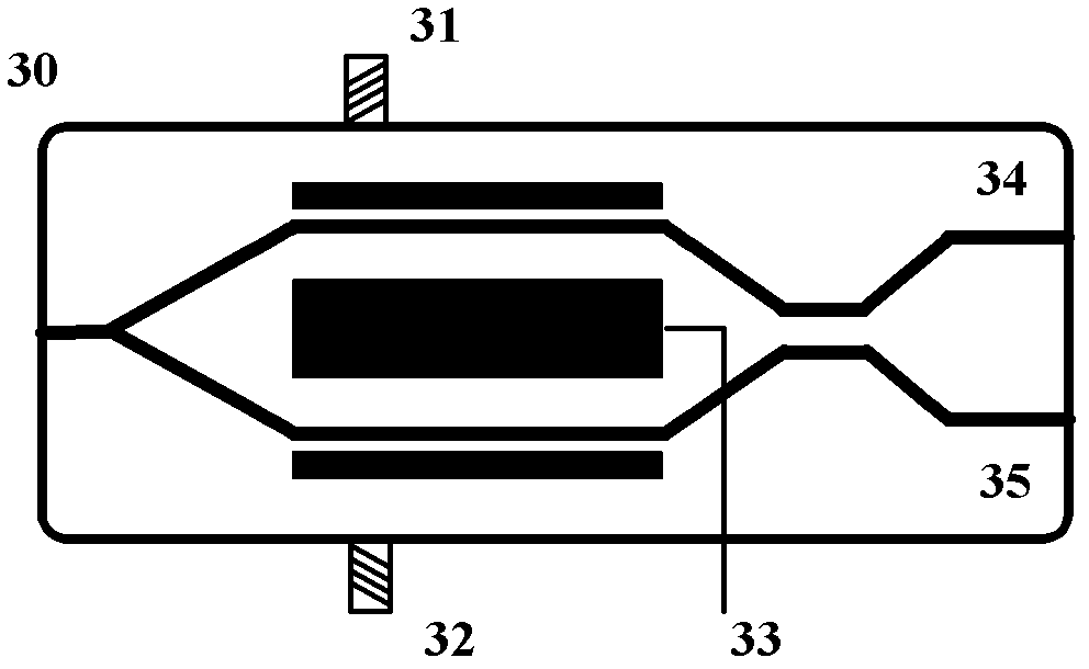
[0033] figure 2 It is a structural diagram of an embodiment of the dual-output intensity modulator used in the present invention, which is a non-push-pull structure, including two RF input ports 31, 32, a DC bias port 33 and two optical output ports 34, 35. The amplitude and phase of the two RF input signals can be set as required, but in order to introduce chirp components, the phase difference between the two signals cannot be set to 180 degrees. In one embodiment, one of the radio frequency input ports is used, and the other radio frequency input port is matched with a 50 ohm resistor, the bias point can be set according to actual needs, and the modulated optical signal is divided in...


PUM


Abstract

The invention discloses a high-frequency broadband radio frequency signal optical fiber zooming system, which comprises a light source, a dual-output intensity modulator, a polarization controller, a polarization beam combiner, an optical fiber and a detector, wherein the light source is used for generating a light carrier; the dual-output intensity modulator is used for modulating a high-frequency broadband radio frequency input signal onto the light carrier and dividing the modulated light signal into two paths to be output from two ports; the polarization controller is connected between the light source and the dual-output intensity modulator and is used for adjusting the polarization state of the light carrier output by the light source to be accordant with a main shaft of the dual-output intensity modulator; the polarization beam combiner is connected with the output port of the dual-output intensity modulator and is used for coupling light signals output from the two ports; the optical fiber is connected with the polarization beam combiner and is used for transmitting a coupled light signal; and the detector is connected with the optical fiber and is used for converting the coupled light signal into an electric signal and recovering the loaded high-frequency broadband radio frequency signal. Due to the adoption of the system, high-performance, low-cost and long-distance high-frequency broadband radio frequency signal optical fiber zooming can be realized.

Description

technical field [0001] The invention relates to the field of microwave photon technology, in particular to a high-frequency broadband radio frequency signal optical fiber remote system. Background technique [0002] Driven by broadband and wireless communication systems in the future, the integration of optical fiber communication technology and wireless communication technology that can carry high-speed data transmission services is an inevitable trend, so the use of optical fiber to transmit analog radio frequency signals has become an extremely important information in various applications delivery method. The analog optical fiber link has a wide range of application requirements in the remote end of the antenna and various optical fiber systems. Compared with traditional coaxial cables, optical fibers have many advantages such as good tensile strength, small size, light weight, wide frequency band, large communication capacity, and anti-electromagnetic interference. Ho...

Claims


Application Information

Patent Timeline
Patent Type & Authority Patents(China)
IPC IPC(8): H04B10/2575H04W88/08H04B10/29
Inventor 徐坤戴键崔岩段瑞敏伍剑林金桐
Owner BEIJING UNIV OF POSTS & TELECOMM
Why Eureka
Try Eureka