
Optical touch device

A touch device, optical technology, applied in the direction of instrument, electrical digital data processing, data processing input/output process, etc., can solve the problems of general products without suitable structure and inconvenience

Inactive Publication Date: 2011-11-09
WALTOP INT
View PDF5 Cites 7 Cited by
  • Summary
  • Abstract
  • Description
  • Claims
  • Application Information

AI Technical Summary

Problems solved by technology

[0005] It can be seen that the above-mentioned existing optical touch device obviously still has inconvenience and defects in structure and use, and needs to be further improved urgently.
In order to solve the above-mentioned problems, the relevant manufacturers have tried their best to find a solution, but for a long time no suitable design has been developed, and the general product has no suitable structure to solve the above-mentioned problems. This is obviously the relevant industry. Urgent problem

Method used


Image

  • Optical touch device
  • Optical touch device
  • Optical touch device

Examples


Embodiment Construction

[0035] In order to further explain the technical means and effects of the present invention to achieve the intended purpose of the invention, in conjunction with the accompanying drawings and preferred embodiments, the specific implementation, structure, features and features of the optical touch device proposed according to the present invention will be described below. Efficacy, detailed as follows.

[0036] The foregoing and other technical contents, features and effects of the present invention will be clearly presented in the following detailed description of preferred embodiments with reference to the drawings. Through the description of specific implementation methods, the technical means and effects of the present invention to achieve the intended purpose can be understood more deeply and specifically, but the attached drawings are only for reference and description, and are not used to explain the present invention limit.

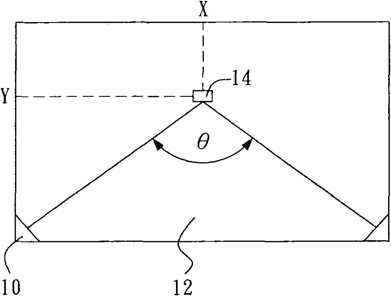
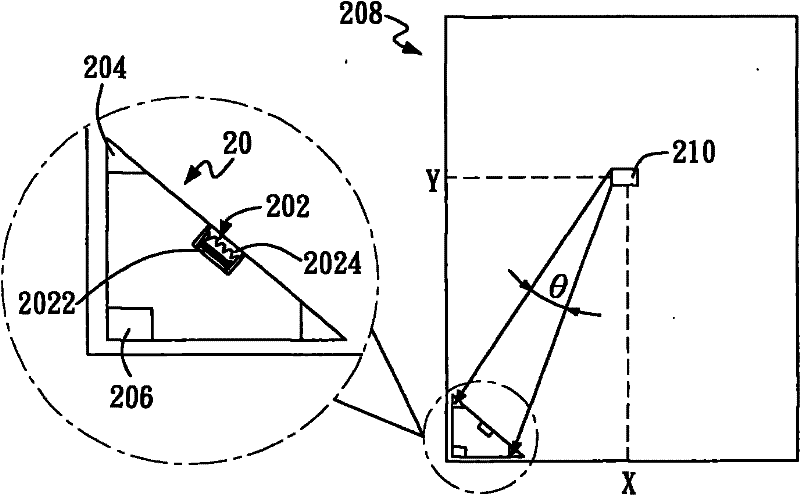
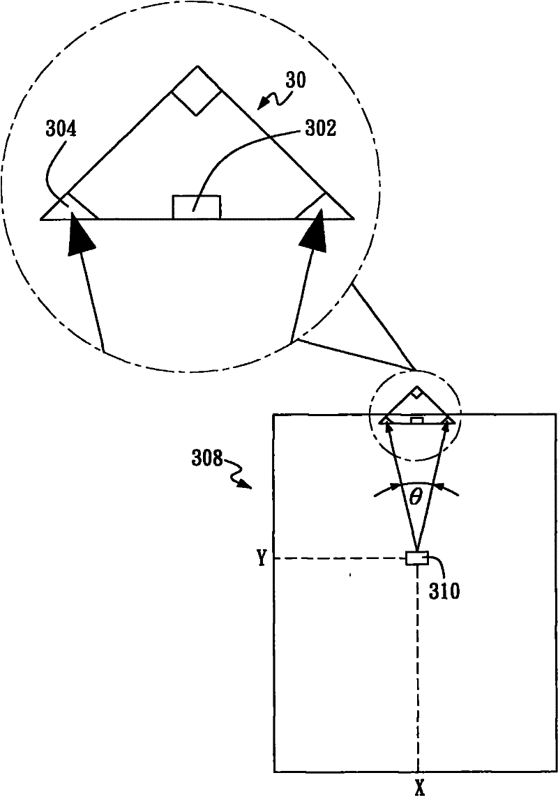
[0037] see figure 2As shown, a schematic ...


PUM


Abstract

The invention relates to an optical touch device, which comprises an infrared laser light source emission module, two infrared light detection modules and a system control module, wherein the infrared laser light source emission module is used for producing an infrared laser light source; the two infrared light detection modules are used for detecting infrared light which is irradiated to a touchobject by an infrared laser light source to be reflected respectively; and the system control module is used for receiving a detection result of the infrared light detection module to judge a coordinate position of the touch object.

Description

technical field [0001] The present invention relates to a touch device, in particular to an optical touch device applicable to different display devices. Background technique [0002] Touch control has become one of the necessary functions of most electronic devices nowadays, and is common in personal digital assistants (Personal Digital Assistant, PDA) and the like. Since the touch function is added to the electronic device, the use of the electronic device becomes easier. Touch technology can be mainly divided into resistive, capacitive and optical. The resistive driving principle is to use the voltage drop to find the coordinates of the touch position, while the capacitive structure uses indium tin oxide (Indium Tin Oxide, ITO) glass as a transparent conductive structure, and its driving principle is based on the ITO glass. Discharge at the four corners to form a uniform electric field on the surface. When a conductive object, such as a finger, makes a small amount of c...

Claims


Application Information

Patent Timeline
Patent Type & Authority Applications(China)
IPC IPC(8): G06F3/042
Inventor 陈威州黄正岱
Owner WALTOP INT
Learn More